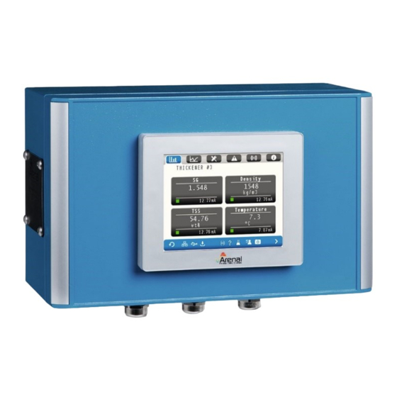
Summary of Contents for Arenal QA03-SDA
- Page 1 Installation Manual Инструкция по установке SLURRY DENSITY ANALYSER плотности суспензий Doc No: KWR-7QA03-921-20220321-EN-RU...
-
Page 2: Table Of Contents
1.4 Electrical cables installation / Установка электрических кабелей ........5 1.4.1 To connect the UDT to the analyser / Подключение UDT к анализатору ..5 1.4.2 Power supply of the QA03-SDA / Источник питания ..........6 1.4.3 mA wiring output / сигналы мА .................. 6 1.4.4 mA wiring input / сигналы... -
Page 3: Preface / Предисловие
QA03-SDA Installation Manual KWR-7QA03-20190503-EN-RU Page 3/16 Preface / ПРЕДИСЛОВИЕ Символы и условные обозначения Symbols and conventions / Caution! This sign indicates that failure to follow directions could result in damage to the equipment or loss of information. Внимание! Этот знак указывает на то, что... -
Page 4: Step 1. Analyser Installation / Шаг 1. Анализатор Установка
QA03-SDA Installation Manual KWR-7QA03-20190503-EN-RU Page 4/16 STEP 1. ANALYSER Installation / ШАГ 1. АНАЛИЗАТОР Установка 1.1 Mounting locations / Монтажные площадки For IP66 built analyser inside canopy Для IP66 встроенный анализатор внутри навеса Temperature Operating: 0-50 degC; Storage: -10ºC to +60ºC Операционная:... -
Page 5: Electrical Cables Installation / Установка Электрических Кабелей
QA03-SDA Installation Manual KWR-7QA03-20190503-EN-RU Page 5/16 Снимите алюминиевые пластины, чтобы установить анализатор на стену Используйте винты и болты «4-монтажного комплекта» для установки анализатора на стену / Установка электрических кабелей 1.4 Electrical cables installation 1.4.1 To connect the UDT to the analyser / Подключение... -
Page 6: Power Supply Of The Qa03-Sda / Источник Питания
QA03-SDA Installation Manual KWR-7QA03-20190503-EN-RU Page 6/16 1.4.2 Power supply of the QA03-SDA / Источник питания 90-263 Vac 50-60 Hz mA wiring output / сигналы мА 1.4.3 On LT4301TADAC display Parameter Terminal on HMI Colour E1 – mA-1 common ground- / Заземление... -
Page 7: Ma Wiring Input / Сигналы Ма
QA03-SDA Installation Manual KWR-7QA03-20190503-EN-RU Page 7/16 mA wiring input / сигналы мА 1.4.4 On LT4301TADAC display Terminal on HMI 4-20 mA input + D13 AND C12 (connect them together) 4-20 mA input - On QM132-IOM Module Terminal on QM132 4-20 mA input 1+... -
Page 8: Open Collector Inputs
QA03-SDA Installation Manual KWR-7QA03-20190503-EN-RU Page 8/16 The output can be powered by the internal power on the main board. Add a second fuse after the power convertor to the 24Vdc connector on the left bottom and wire this to the below mentioned terminals on top of the HMI. - Page 9 QA03-SDA Installation Manual KWR-7QA03-20190503-EN-RU Page 9/16 Wire Terminal on HMI 24Vdc+ Connect + to positive side of your switch. Protect by fuse. 24Vdc GND D3 (IC1) Free D2 (i2) Input switch C3 (I3) Negative side of your switch. Take a sample of the process by pressing this button for 0,5-9 secs.
-
Page 10: Step 2. Spool Piece/Wafer Installation / Шаг 2. Анализатор Установка
QA03-SDA Installation Manual KWR-7QA03-20190503-EN-RU Page 10/16 STEP 2. Spool piece/wafer Installation / ШАГ 2. АНАЛИЗАТОР Установка 2.1 Mounting position / Монтажное положение a. In vertical pipe, mounting position is not relevant В вертикальной трубе монтажное положение не имеет значения In horizontal pipe, mounting position must be as in the picture: В... -
Page 11: Mounting Location / Место Установки
QA03-SDA Installation Manual KWR-7QA03-20190503-EN-RU Page 11/16 / место установки 2.2 mounting location a. Mounting 7x diameter after last obstruction and 5x diameter before next obstruction (pump, bend, narrowing, valve) Монтаж диаметром 7x после последней обструкции и 5-кратным диаметром перед следующим препятствием (насос, изгиб, сужение, клапан) -
Page 12: Step 3. Start Up
QA03-SDA Installation Manual KWR-7QA03-20190503-EN-RU Page 12/16 STEP 3. Start up Start up and commissioning by unauthaurised personnel is at own risk. During start up, when the mA outputs are not connected,an error code is shown. Simply press the X to remove the error and it won’t show up anymore. -
Page 13: Step 4. Correcting Ma Outputs
QA03-SDA Installation Manual KWR-7QA03-20190503-EN-RU Page 13/16 STEP 4. Correcting mA outputs a) The mA output of the SG and the Density is not the same. To get these the same, follow below instructions. b) Press the SG box in above picture, the following menu will open with a prompt for a level 2 User ID and Password code in order to gain access. - Page 14 QA03-SDA Installation Manual KWR-7QA03-20190503-EN-RU Page 14/16 d) The keypad will open again for the password. Type 07AF as the password and press enter, which will then take you back to the level 2 menu as above, but now indicating both the user ID (EL) and the password as ****.
- Page 15 QA03-SDA Installation Manual KWR-7QA03-20190503-EN-RU Page 15/16 g) Press DENSITY h) Make sure all settings are as above. Then Press > to go to following screen. i) The 4-20 mA value is 17,24 because the range is here 1000..1800 (while SG was 1..2).
- Page 16 QA03-SDA Installation Manual KWR-7QA03-20190503-EN-RU Page 16/16...


Need help?
Do you have a question about the QA03-SDA and is the answer not in the manual?
Questions and answers