
Related Manuals for Meterman PM53


Summary of Contents for Meterman PM53
- Page 1 PM53 Automatic Pocket Meter Users Manual • Mode d’emploi • Bedienungshandbuch • Manual d’Uso • Manual de uso PN 2153036 August 2004 2004 Meterman Test Tools. All rights reserved. Printed in Taiwan...
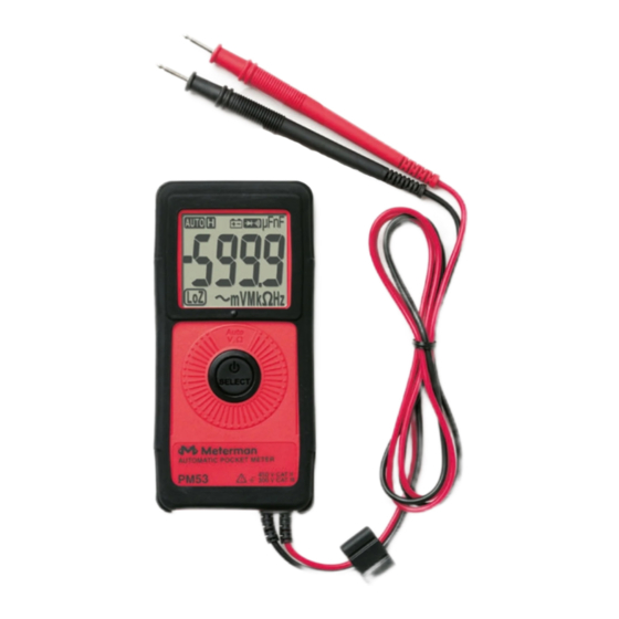
- Page 2 Press for 2 seconds to turn meter on. LCD display SELECT-button to select alternate functions and turn the power off and on. Permanently attached red test lead for positive (+) polarity and black test lead for ground reference (-)
-
Page 3: Table Of Contents
PM53 Pocket Meter Contents Introduction Safety Information Symbols Used in this Manual Turning the Meter On and Off Making Measurements AutoTect Mode Continuity, Audible With Symbolic Display Electric Field EF-Detection, VolTect Voltage Resistance Frequency Capacitance Product Maintenance Maintenance Cleaning Troubleshooting... -
Page 4: Introduction
This unique meter has a full complement of features in a compact package only 3/8 inch deep and weighing less than 3 oz. The essential shirt-pocket size meter for portability, Model PM53 is fully autoranging and has an oversized, easy-to-read digital display. It offers the AutoTect™ feature that guides the meter to display AC volts, DC volts or resistance based on what you are measuring. -
Page 5: Symbols Used In This Manual
Symbols Used in this Manual Battery Refer to the manual Double insulated Dangerous Voltage Direct Current Earth Ground Alternating Current Audible tone > Underwriter Laboratories, Complies with EU directives Inc. I Fuse Turning the Meter On and Off • Press the SELECT button for approximately 2 seconds to turn the meter •... -
Page 6: Making Measurements
Making Measurements All measurements described in this manual use the Red test lead for positive (+) polarity and Black test lead for Ground reference (-) unless otherwise specified AutoTect mode is the default function when the meter is first turned on. Press the SELECT button momentarily to select and step through the functions: •... -
Page 7: Autotect Mode
AutoTect Mode The AutoTect feature automatically selects measurement function of V dc, V ac, or resistance based on the input via the test leads. ● With no input, the meter displays Auto when it is ready. ● With no voltage signal but a resistance below 6 MΩ is present, the meter displays the resistance value. - Page 8 strength is indicated as a series of bargraph segments on the display and variable beep tones. See the VolTect specifications later in this manual for a complete description of the bar graph indicators. • Voltect An antenna is located at the top left corner of the meter, which detects electric field surrounding current-carrying conductors.
- Page 9 Note For Maximum sensitivity, hold the meter away from the VolTect corner.
-
Page 10: Voltage
Voltage With Auto on the LCD, press the SELECT button 3 times to select V ac function. The meter displays LoZBV when it is ready.This function is auto-ranging. With Auto on the LCD, press the SELECT button 4 times to select V dc. The meter displays LoZ V when it is ready. -
Page 11: Troubleshooting
Troubleshooting If the instrument fails to operate, check battery, leads, and replace battery as necessary. Double-check operating procedure as described earlier in this manual. If the display locks up, press the SELECT button for approximately 6 seconds to reset the microprocessor. If the instrument’s voltage-resistance input is subjected to high voltage transient (mostly caused by lightning or switching surge to your system) by accident or abnormal conditions of operation, the series fusible resistors... -
Page 12: Limited Warranty And Limitation Of Liability
Please check the “Where to Buy” section on www.metermantesttools.com for a list of distributors near you. Additionally, in the United States and Canada In-Warranty repair and replacement units can also be sent to a Meterman Test Tools Service Center (see below for address). -
Page 13: Specifications
Non-Warranty Repairs and Replacement – US and Canada Non-warranty repairs in the United States and Canada should be sent to a Meterman Test Tools Service Center. Call Meterman Test Tools or inquire at your point of purchase for current repair and replacement rates. - Page 14 Power Supply: 3 V standard button battery x 1 (IEC-CR2032; ANSI-NEDA- 5004LC) Power Consumption (typical): 2 mA APO Consumption (typical): 2.2 µA APO Timing: Idle for 3 minutes Dimension / Weight L 113 mm x W 53 mm x H 10.2 mm / Approx. 78 gm Special Features AutoTect...
- Page 15 DC Voltage Range Accuracy ±(0.5%+3 dgt) 6.000 V ±(1.0%+5 dgt) 60.00 V ±(1.2%+5 dgt) 450.0 V Input Impedance: AutoTect Lo-Z V dc: 160 kΩ, 160 pF nominal MRR: > 30dB @ 50 Hz/60 Hz CMRR: > 100dB @ DC, 50 Hz/60 Hz; Rs=1 kΩ V dc AutoTect...
- Page 16 Capacitance Range Accuracy 100.0 nF, 1000 nF, 10.00 µF, ±(3.5%+6 dgt) 100.0 µF Accuracy below 50 nF is not specified Accuracies with film capacitor or better Top range. Updates > 1 minute on large values Specified with battery voltage above 2.8 V (half full battery). Accuracy decreases gradually to 12% at low battery warning voltage of approx.
- Page 17 Frequency Range Accuracy Specified At 100 Hz, 1 kHz, and 10 < 20 V Sine-rms ±(0.5%+4 dgt) Sensitivity (Sine-rms): Hz in Auto-VΩ position:> 3 V Voltect Typical Voltage Bar Graph Indication 15 V to 55 V 30 V to 85 V - - - 45 V to 145 V - - - -...
Need help?
Do you have a question about the PM53 and is the answer not in the manual?
Questions and answers