
Related Manuals for TriCom 11000-00897


Summary of Contents for TriCom 11000-00897
- Page 1 OPERATOR'S MANUAL TCR-SPK-DUALv2 AMPLIFIED DUAL-NET SPEAKER DOCUMENT # 90400-01480 • Tricom Research, Inc. www.tricomresearch.com 17791 Sky Park Circle, Suite J, Irvine, CA 92614 Phone: (949) 250-6024 Fax: (949) 250-6023...
- Page 2 TCR-SPK-DUALv2 OPERATOR'S MANUAL Revision History - Document 90400-01480 REVISION DESCRIPTION DATE INITIAL RELEASE 12 SEPTEMBER 2020 UPDATED TABLE 1-2 WITH 5 VDC MIC BIAS 15 MARCH 2022 UPDATED APPLICABLE SECTIONS TO REFLECT 16 AUGUST 2022 CONNECTOR CHANGE Note: The latest version of this manual can be downloaded from our website at www.tricomresearch.com.
-
Page 3: Table Of Contents
TCR-SPK-DUALv2 OPERATOR'S MANUAL TABLE OF CONTENTS INTRODUCTION General Information ....................1 Abbreviations And Glossary ..................2 Speaker ........................3 Cables ........................3 Specifications ......................3 OPERATION General Information ....................5 Controls ........................5 Power On, Initialization, And Set Up ............... 5 Pushbutton Functions .................... -
Page 4: Introduction General Information
INTRODUCTION GENERAL INFORMATION The TCR-SPK-DUALv2 is the next generation of Tricom's Amplified Dual-Net Tactical Speaker. As one of the smallest and most capable amplified speakers on the market, the TCR-SPK-DUALv2 easily integrates into vehicular, maritime, airborne, and fixed station applications. The speaker amplifies two tactical radio nets with intuitive operation, enables simultaneous transmit across both nets, and supports up to two handsets per net. -
Page 5: Abbreviations And Glossary
ABBREVIATIONS AND GLOSSARY Automatic Gain Control CONN Connector Decibel Ground HDST Handset Hertz Input/Output Kilohertz Light Emitting Diode Push to Talk Receive Volts, Direct Current Watt Transmit... -
Page 6: Speaker
SPEAKER The TCR-SPK-DUALv2 Amplified Dual-Net Speaker has a sealed, rugged enclosure finished in black anodize and designed to withstand the elements and resist corrosion. The enclosure houses all electronic subassemblies. CABLES Five multi-conductor cables connect the speaker to the DC power, communications system(s), and handsets. -
Page 7: Table 1-2. Interconnect Characteristics
Table 1-2. Interconnect Characteristics CONN SIGNAL/PIN DETAIL POWER Power/Auxiliary Hirose HR30-6R-6P(71) Pin 1 VDC+ Pin 2 Electrical Ground (GND) Pin 3 Optional Slave Speaker + Pin 4 Optional Slave Speaker - Pin 5 Spare Pin 6 Not Connected HDST A Handset(s) Hirose HR30-7R-12P(31) (MAIN A/B) -
Page 8: Operation
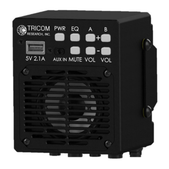
OPERATION GENERAL INFORMATION The TCR-SPK-DUALv2 can be used for operation once it has been installed, as described in Section 3. CONTROLS The TCR-SPK-DUALv2 has an intuitive front panel with seven buttons, as shown in Table 2-1: Table 2-1. Front Panel Controls CONTROLS TYPE FUNCTION... - Page 9 the speaker is on. Press and hold the PWR button for more than two seconds to power down the speaker. While off, handset and radio connections are straight pass-throughs enabling communication using the handsets. PWR Pushbutton – Brightness - To change the brightness of button backlighting, press the PWR button momentarily.
-
Page 10: Usb Charging Port
USB CHARGING PORT The USB charging port is provided for charging USB devices only. The port provides 5 VDC and up to 2.1A for charging. AUXILIARY AUDIO PORT The TCR-SPK-DUALv2 has a standard 3.5mm auxiliary audio-in port for audio playback. Audio playback is automatically muted with incoming radio traffic or handset PTT. -
Page 11: Figure 3-1. Tcr-Spk-Dualv2 Outline Drawing (W/ Mount)
Figure 3-1. TCR-SPK-DUALv2 Outline Drawing (w/ Mount) Figure 3-2. TCR-SPK-DUALv2 Outline Drawing (w/o Mount) -
Page 12: Dc Input Power
DC INPUT POWER The DC input power connector, shown in Figure 3-3, is compatible with a specific power cable fitted with a matching Hirose female connector. A typical power cable is shown in Figure 3-4. Note that the speaker has true reverse polarity protection, including protection from connecting the positive voltage input to Pin B (GND) with a grounded chassis. -
Page 13: Radio Interfaces
RADIO INTERFACES The speaker can connect to two radios, labeled RADIO A and RADIO B. HANDSET INTERFACES The speaker has two handset cable connectors labeled HDST A (MAIN A/B) and HDST B (AUX A/B). If the integration requires only 2 handsets, 1 for Radio A and 1 for Radio B, then the HDST A and HDST B cables will be used.
Need help?
Do you have a question about the 11000-00897 and is the answer not in the manual?
Questions and answers