
Subscribe to Our Youtube Channel
Related Manuals for CTC Union SC310 Series

Summary of Contents for CTC Union SC310 Series
- Page 1 SC310 Series Signal Conditioner SC310 Series Signal Conditioner Product Manual Product Manual...
-
Page 2: Table Of Contents
Table of Contents • Introduction . . . . . . . . . . . . . . . . . . . . . . . . . . . . . . . . . . . . . . . . . . . . . . . . . . . . . . . . . . . . . . . . . . .3 •... -
Page 3: Introduction
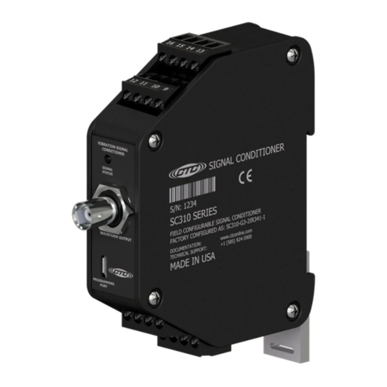
Introduction This document contains information on the operation, installation, and maintenance of the SC310 Series Signal Conditioner . The signal conditioner is a device that converts a sensor input to 0-20 mA, 4-20 mA, 0-5 V , or 0-10 V output signals and provides a buffered dynamic output of the vibration waveform . -
Page 4: Installation
• Output selectable between acceleration, velocity, or displacement (varies by configuration) • Ten available full-scale ranges from 0 .5 to 500 (g’s, IPS, mm/sec, mils; the maximum full-scale range varies based on input sensor activity) • Two buffered dynamic outputs, one via BNC and one via terminal blocks •... - Page 5 Connect the +20 - 32 V power lead to the terminal marked 5 and the negative or common to the terminal marked 6 . For single channel accelerometer input connection, wire the sensor leads to 13(+), 14(-), and 15(shield drain wire) as shown in Figure 1 . If using a TA series sensor, the temperature out lead is attached to terminal 16 .
- Page 6 Wiring for Biaxial/Triaxial Accelerometers The SC300 Series signal conditioners are compatible with biaxial and triaxial sensors; however, the wiring will be different than connecting a single-axis accelerometer or piezo-velocity sensor . Each vibration input will require a unique signal conditioner, so a triaxial sensor will require three SC300 units, and each biaxial sensor will require two SC300 units .
-
Page 7: Signal Conditioner Configuration
Signal Conditioner Configuration Requirements • Windows 10 minimum build version: 1703 or .NET Framework 4 .7 .2 (https:// dotnet.microsoft.com/download/dotnet-framework/thank-you/net472- web-installer) • Approximately 1GB of free storage (5GB recommended) to create application files, log files, and database records . Installing the Configuration Software Log into your account on the CTC website . - Page 8 A compressed .zip folder will download . Find this in your browser’s download manager and open the file . A window may pop up asking about compressed folders . Click Extract all . Double click the .exe file located in the folder to launch the installer . Windows security might attempt to block the installer on launch .
- Page 9 Read and accept the licence . Click Next . Review the system requirements . Click Next . Review the location for the program files to be installed . If a different location is preferred, click Browse, and set the new destination . Click Next . By default, the program will add a launch button to the Windows Start Menu .
- Page 10 If a desktop icon is desired, click the “Create a desktop shortcut” checkbox . Click Next . For ease of access, it is highly recommended to include either a desktop icon or a Windows Start Menu launcher . If neither of these options were included during installation, it is still possible to launch the software by typing “Signal Conditioner Configurator”...
- Page 11 Running the application When you run the CTC Signal Conditioner Application, the first thing that will appear is a device select screen . This is where all units currently plugged into the computer will appear . If no Signal conditioners are plugged in to the computer, a pop up window will display requesting that one be connected .
- Page 12 Configuration Software There are several different controls for changing the configuration of the selected device . The Part Number text box will display the part number for the currently selected configuration values . The Part Number text box will also change the selected configuration values if a part number is typed or pasted into the box .
- Page 13 . Below, the “IEPE Power” dropdown menu is where each channel’s scaling settings are configured . For the SC310 series, only Channel 1 will be available to edit . “Full-Scale Range” corresponds to the dynamic range of the measurement and, combined with “Output Units,”...
- Page 14 The “Output Type” dropdown determines what kind of process signal each channel will output . Selectable options are 0-20 mA, 4-20 mA, 0-5 V , and 0-10 V . The level of the output signal corresponds to where it falls in the full- scale range .
- Page 15 Figure 4. Update Firmware The Diagnostics tab shown in Figure 5 is where device errors and warnings can be read off the signal conditioner (see Indicators in the Operation section) by clicking “View Errors .” If errors are present on the device, View Errors will read them and display information about the error(s) for corrective action .
- Page 16 Accessing Configuration History Clicking “File” in the top menu will allow the user to select an option to view previous configurations . Selecting this option will open the computer’s default text file viewer with a log containing the date, time, serial number, part number, and full configuration .
-
Page 17: Operation
Operation Once all wires are connected, apply power to begin operating the signal conditioner . Make sure the status light settles to normal mode . Note: When the software reports an error, it does not necessarily mean that the error is currently present on the signal conditioner . It just means that the error has been encountered at some time and recorded for reporting . - Page 18 State 4 - Device Warning Detected • LED is flashing green in 1-second intervals A detected warning can be due to several things, such as incorrect output wiring (e .g ., an open circuit detected on a current output or a short circuit detected on a voltage output) or corrupted configuration memory .
- Page 19 Temperature Output Guide This chart is for reference purposes only and illustrates typical temperature output signal behavior . This chart is not based on actual test results, nor does it map an exact voltage from the temperature sensor to an exact 4-20 mA value . This functionality is only applicable with a CTC TA200 Series dual output sensor .
- Page 20 Portable Data Collector Interfacing When collecting waveform data from the BNC jack on the signal conditioner using a portable data collector that supplies constant current power, it is recommended that the data collector is configured so that power to the sensor is turned off . Although the BNC connector circuitry offers short circuit protection and can safely sink the current, long-term degradation may occur due to increased power dissipation depending on the magnitude of the IEPE current .
-
Page 21: Verifying Driver Support For Configuration
Verifying Driver Support for Configuration If the SC300 is correctly connected via USB and the software properly installed, the serial number of the device will appear in the dropdown menu . If a serial number doesn’t appear, follow the troubleshooting steps below . •... - Page 22 Look for and select the “Other Devices” option, then right-click on “USB Serial Port .” Select the “Update Driver” option . Select “Search Automatically for Drivers,” and the computer should search for and install the necessary driver . If the driver updates correctly, there will no longer be a “USB Serial Port” option in the “Other Devices”...
- Page 23 If a notification appears that there is no available upgrade, the driver will have to be installed manually . The first step is to go to the link below – https://ftdichip.com/drivers/vcp-drivers/ Scroll down to the download link section and select the setup executable option on the left side .
- Page 24 A standard installation wizard will open . Follow it to completion . When this is complete, return to the Device Manager . If all is correct, USB Serial Port (COMX) will be displayed in the Ports section of the drop-down menu . When this appears, open the CTC Signal Conditioner program .
-
Page 25: Troubleshooting
Troubleshooting Troubleshooting the Software Problem Description Recommended Actions Verify that the minimum requirements for the software are met . Application does not open Reinstall the software . Read the log file located in the install directory . Make sure the drivers for the device are installed . - Page 26 Troubleshooting Troubleshooting the Hardware Problem Description Recommended Actions Check status LED; ensure signal conditioner is in Normal mode . Ensure it was correctly programmed and 4-20 mA or 0-5/10 V output is make sure all wiring is correct . Refer non-functional to Figure 1 for wiring diagram .
- Page 27 Problem Description Recommended Actions Check output wiring, ensure connections are present and secure, there are no breaks in the wires, and Open circuit detected on CH1 there is no exposed conductors that can cause short circuits . Ensure that the end measurement device (DCS, DAQ, PLC, multimeter, etc .) is correctly configured to read Short circuit detected on CH1...
- Page 28 Problem Description Recommended Actions Ensure that the connection to the PC is secure and did not come loose during programming . Also make sure that the signal conditioner does not No response from signal conditioner lose power during programming . when programming LED status light should remain solid orange while plugged in .
-
Page 29: Software End User Agreement
Software End User License Agreement This END USER LICENSE AGREEMENT (“Agreement”), is a binding agreement between Connection Technology Center, Inc ., a New York corporation, with offices at 7939 Raw Boulevard, Victor, NY 14564 (“CTC”) and the entity registered with CTC (“Licensee”) as the purchaser of the SC300 Series signal conditioner (the “Signal Conditioner”) . - Page 30 rights granted, applied for, or otherwise now or hereafter in existence under or related to any patent, copyright, trademark, trade secret, database protection, or other intellectual property rights laws, and all similar or equivalent rights or forms of protection, in any part of the world . “Internal Business Purposes”...
- Page 31 (“Third-Party Licenses”) . A list of all materials, if any, included in the Software and provided under Third-Party Licenses is set forth on Schedule A to this Agreement, and the applicable Third-Party Licenses are accessible via links therefrom . Licensee is bound by and shall comply with all Third-Party Licenses .
- Page 32 other transport management systems; (iii) safety-critical applications, including medical or life-support systems, vehicle operation applications, or any police, fire, or other safety response systems; and (iv) military or aerospace applications, weapons systems, or environments; ( j) use the Software or Documentation in violation of any law, regulation, or rule;...
- Page 33 license, convey or otherwise alter or deprive CTC of any of its Intellectual Property Rights . (b) Licensee shall use commercially reasonable efforts to safeguard Software (including copies thereof) from infringement, misappropriation, theft, misuse, or unauthorized access . Licensee shall promptly notify CTC if Licensee becomes aware of any infringement of CTC’s Intellectual Property Rights in the Software or Documentation and reasonably cooperate with CTC in any legal action taken by CTC to...
- Page 34 9 . Limited Warranty, Exclusive Remedy, and Disclaimer/Warranty Disclaimer . (a) The Software, when properly installed on a computer meeting the specifications set forth in and operated in accordance with the Documentation, will perform in accordance with the Documentation, in all material respects .
- Page 35 (A) CONSEQUENTIAL, INCIDENTAL, INDIRECT, EXEMPLARY, SPECIAL, ENHANCED, OR PUNITIVE DAMAGES; (B) INCREASED COSTS, DIMINUTION IN VALUE OR LOST BUSINESS, PRODUCTION, REVENUES, OR PROFITS; (C) LOSS OF GOODWILL OR REPUTATION; (D) USE, INABILITY TO USE, LOSS, INTERRUPTION, DELAY OR RECOVERY OF ANY DATA, OR BREACH OF DATA OR SYSTEM SECURITY;...
- Page 36 Licensee . Licensee will employ at least the same methods and degree of care, but no less than a reasonable degree of care, to prevent disclosure of the Confidential Information as Licensee employs with respect to its own confidential information . (c) Upon CTC’s written request, Licensee shall destroy or return to CTC all Confidential Information in its custody or control .
- Page 37 constitute an impermissible assignment . This Agreement is binding upon and inures to the benefit of the Parties hereto and their respective permitted successors and assigns . (d) Governing Law . This Agreement is governed by and construed in accordance with the internal laws of the State of New York without giving effect to any choice or conflict of law provision or rule that would require or permit the application of the laws of any jurisdiction other than those of the State of New York .
- Page 38 (i) Interpretative Provisions . The words “hereof”, “herein” and “hereunder” and words of like import used in this Agreement shall refer to this Agreement as a whole and not to any particular provision of this Agreement . The captions herein are included for convenience of reference only and shall be ignored in the construction or interpretation hereof .
-
Page 39: Maintenance
Maintenance There are no customer replaceable parts on the signal conditioner . The device has been designed to self calibrate and monitor its own operational status . It is designed to provide trouble-free continuous service under normal operating conditions . Should the instrument require repair, visit ctconline .com for a return material authorization .
Need help?
Do you have a question about the SC310 Series and is the answer not in the manual?
Questions and answers