Table of Contents
Advertisement
Quick Links
Advertisement
Table of Contents

Summary of Contents for Mul-t-lock KC5
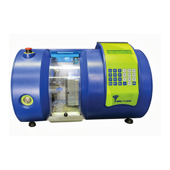
- Page 1 Computerized Key-Cutting Machine USER OPERATION MANUAL...
-
Page 2: Table Of Contents
Safety Notes for Lifting and Transport ....18 4.2. Packing Instructions ..........19 4.3. Packing Dimensions ..........24 4.4. Transporting Instructions .......... 25 4.5. Uncrating ..............27 4.6. Installation Area Features ........28 4.7. Receiving Inspection ..........28 KC5™ Key Cutting Machine User Manual... - Page 3 Table of Contents 5. Functional Description The Major Parts of the Machine ................30 5.1. General ......................31 5.1.1. PLC ...................... 31 5.1.2 HMI LCD and Keypad ................31 5.2. General Machine View .................. 32 5.3. X and Y Unit: ....................
- Page 4 8.1 Spare Parts List .............. 87 8.2 Data Record Table for Axis OFFSET ......89 8.3 Depth Measurements for Key Combination Cut ..90 8.4 Troubleshooting .............. 91 8.5 Motor Belt Tensioning ........... 94 KC5™ Key Cutting Machine User Manual...
-
Page 5: Message From Mul-T-Lock
1.1. Message From Mul-T-Lock: The KC5 represents a new generation of high efficiency key cutting machines. As a world leader in the field, Mul-T-Lock takes the pride in providing the best quality, and the most efficient high security products, for locksmiths. -
Page 6: Terms Of Usage
Introduction Safety Notices 1.2. Terms of Usage ® The right and license to cut keys for Mul-T-Lock Ltd. products is subject at all times to the terms in the agreement between the buyer System ® Specifications of the KC5 Key Cutting Machine and Mul-T-Lock Ltd. -
Page 7: User Language Translation
® After receiving the machine from Mul-T-Lock Technologies Ltd., the user may contact Mul-T-Lock Service Department and ask for permission to translate this manual into the user’s language. ® The applicant will fill in and send the form obtained from the Mul-T-Lock Technologies Ltd. -
Page 8: Safety Notices
We advise strict observance of the work safety standard as defined by the relative authorities in each nation. The manufacturers accept no responsibility for damage to persons or objects resulting from noncompliance of safety standards. KC5™ Key Cutting Machine User Manual – 7 –... -
Page 9: Safety Notes For Machine Use
Safety Notices 2.2. Safety Notes for Machine Use WARNING The following safety practices must be complied with: • CAUTION and WARNING notices posted on the machine and safety notes in this manual. • Only qualified and certified personnel may operate the machine and/or perform maintenance on the machine. - Page 10 WARNING • HOT SURFACES: Some motors might have hot surface after running. Maintenance Unauthorized personnel may not remove covers. If a cover was removed do not touch. Appendixes KC5™ Key Cutting Machine User Manual – 9 –...
-
Page 11: Safety Notes Concerning Maintenance
Carefully read the user and maintenance instructions manual before beginning or using the machine, or effecting machine or plant maintenance or tool replacement tasks. Use only Mul-T-Lock original spare parts, cutting tools and accessories supplied with the ® machine or purchased directly from Mul-T-Lock Technologies Ltd. -
Page 12: System Specifications
Introduction 3. System Specifications Safety Notices 3.1. General This manual describes the working procedures for the KC5 - Key System Cutting Machine. All machine components, their functional correlation, Specifications power requirements, and other relevant descriptions are detailed and illustrated here to provide the operator with a thorough understanding of the system and of the proper maintenance and safety procedures, thereby minimizing machine downtime. -
Page 13: Machine Layout And Measurements
System Specifications 3.2. Machine Layout and Measurements Top view D = 340 W = 525 – 12 –... - Page 14 Introduction Safety Notices Front view System Specifications Packing and Transportation H = 360 Functional Description Operator Manual Maintenance Appendixes KC5™ Key Cutting Machine User Manual – 13 –...
-
Page 15: Weight
System Specifications 3.3. Weight Machine (net) weight: 32 Kg. Packing box (tare) weight: 7 Kg. Packed unit weight: 39 Kg. 3.4. Service Environmental Requirements We recommend preparing the working site in advance. Some requirements include future arrangements and we recommend carrying out basic preparation for installation before the machine arrives, especially any work that generates dust. -
Page 16: Internet Wall Socket
For other tasks on the machine, such as cleaning or tool replacement, a stronger light is needed. Install a regular 100 Watt bulb light about 1 meter above the machine or add suitable strong light nearby. KC5™ Key Cutting Machine User Manual – 15 –... -
Page 17: Electric Cable (Plug And Socket)
System Specifications 3.4.8. Electric cable (plug and socket) Electric cable/cord is supplied with the machine. The cable is a regular 10 Ampere cable. Consult your local electrician for any advice. The electric cable/cord socket side – 16 –... -
Page 18: Machine Label
The machine noise level is low and normal. The level is below 80 dbA. The use of ear protection is not mandatory, but ear protection is Maintenance recommended for prolonged usage. Appendixes KC5™ Key Cutting Machine User Manual – 17 –... -
Page 19: Packing And Transporting
4. Packing and Transporting 4.1. Safety Notes for Lifting and Transport WARNING The manufacturer bears no responsibility for any damage to objects or persons caused by non-compliance with the applicable safety standards in force relating to the lifting and movement of material within the user’s factory. Machine transfer and truck loading must only be carried out with the appropriate equipment as described in the Packing &... -
Page 20: Packing Instructions
Transportation The machine is attached to a bench with four metal brackets. Use two screws for each bracket. Functional Description Operator Manual Maintenance Appendixes KC5™ Key Cutting Machine User Manual – 19 –... - Page 21 Packing and Transporting Install axis fixing jig. Attach machine with 4 metal brackets. Use two screws for each bracket. – 20 –...
- Page 22 Safety Notices Safety Notices Cover the machine with the plastic sheet. System System Specifications Specifications Packing and Transportation Functional Description Operator Manual Place foamed plastic plates around the machine. Maintenance Appendixes KC5™ Key Cutting Machine User Manual – 21 –...
- Page 23 Packing and Transporting Place cardboard over the machine and wrap with plastic strips. Mark the box with the sticker. Components to be packed: • Main Unit • Accessories – 22 –...
- Page 24 • “Very Fragile”, “Do not stack”, “Avoid humidity”. • Description of the crate content. Appendixes • Full details of the crate destination. • “Lift from this side” - to indicate the lifting direction. KC5™ Key Cutting Machine User Manual – 23 –...
-
Page 25: Packing Dimensions
Packing and Transporting 4.3. Packing Dimensions Overall dimensions: Width: 620 mm Depth: 400 mm Height: 470 mm – 24 –... -
Page 26: Transporting Instructions
When the crate arrives at the user’s site, it must be handled with extreme care, outside and indoors, using suitable equipment for crate’s weight. a. Forklift Maintenance b. Other mechanical means Appendixes KC5™ Key Cutting Machine User Manual – 25 –... - Page 27 Packing and Transporting WARNING Avoid manual handling, protect your back. If manual work is mandatory, employ a minimum of two workers for handling. – 26 –...
-
Page 28: Uncrating
(see page 22). • Remove the machine from the wooden bench and place it securely on a suitable surface. The KC5 machine arrives fully assembled. Hold the Operator Manual machine base firmly and lift onto the workbench designated for its use, handling with care. -
Page 29: Installation Area Features
Packing and Transporting 4.6. Installation Area Features WARNING Make sure that the load-bearing capacity of the table or desk is suitable for machine overall weight. The overall machine dimensions must be carefully considered to ensure rational installation. The machine should preferably be located in an area that gives access from all sides. The work area must be well lighted and equipped with telephone line, Internet connection and suitable electrical sockets. - Page 30 Introduction Safety Notices Safety Notices • Check to package contains: № Description Check System System Key Cutting Machine KC5 Specifications Specifications Machine and software operation manual Packing and Installation and manual CD kit Transportation 2 Keys for machine key switch...
-
Page 31: Functional Description
5. Functional Description The key cutting machine is a 3-axis CNC machine. The Machine includes three motors to activate each axis and one spindle motor to activate the cutting tools. The machine includes a PLC to control all movements of the machine. To operate the machine the operator uses the HMI includes the LCD and the Keypad. -
Page 32: General
• To display the information on the LCD screen and on all the other screens. • To serve as an operating panel for the machine’s operator. • To manage jobs and to operate standard machine jobs. Appendixes KC5™ Key Cutting Machine User Manual – 31 –... -
Page 33: General Machine View
Functional Description 5.2. General Machine View – 32 –... - Page 34 Card Reader System System Specifications Specifications Y axe Packing and Transportation Spindle X axis Motor Functional Description Operator Manual Cutters Unit Belt Pulley General front view – covers removed Maintenance Appendixes KC5™ Key Cutting Machine User Manual – 33 –...
- Page 35 Functional Description General rear view – 34 –...
- Page 36 Safety Notices Safety Notices Controller Card reader System System Specifications Specifications Packing and Transportation Functional Description Operator Manual X axis motor Power Supply Maintenance General rear view – covers removed Appendixes KC5™ Key Cutting Machine User Manual – 35 –...
-
Page 37: And Y Unit
Functional Description 5.3. X and Y Unit Y axis motor X axis Motor X axis sensor Y axis sensor Y axis X axis X and Y Unit – Covers Removed – 36 –... -
Page 38: Z Station
The BLDC driver unit is supplying 24 volts operating voltage to the Appendixes required systems and assembled at the right side of the electronic panel. The BDLC driver gets its command directly from the system controller output. KC5™ Key Cutting Machine User Manual – 37 –... - Page 39 Functional Description Z axis Probe Z axis sensor Z axis sensor – 38 –...
-
Page 40: Metal Chips Drawer
Safety Notices 5.5. Metal Chips Drawer System System Specifications Specifications Packing and Transportation Functional Description Operator Manual The metal chips drawer used for collecting metal chips from the cutting Maintenance process. Appendixes KC5™ Key Cutting Machine User Manual – 39 –... -
Page 41: Spindle Motor And Cutting Tools Station
Functional Description 5.6. Spindle Motor and Cutting Tools Station Spindle Motor Belt Pulley Belt tension screw Spindle motor and cutting tool unit • The spindle motor turns all three cutters together. • The motor uses a belt to turn the pulley. • Refer to next page to see tool replacement. -
Page 42: Change Cutting Tools
Safety Notices Safety Notices 5.7. Cutting Tools System System Specifications Specifications № 1 – External cutter Packing and Transportation Sensor probe № 2 - Internal cutter Functional Description Marker № 3 – "Snake" cutter Operator Manual Maintenance Tools names - locations and numbers Appendixes KC5™ Key Cutting Machine User Manual – 41 –... - Page 43 Functional Description Tool replacement Cutter № 1 Cutter № 2 Cutter № 3 Tool pictures – 42 –...
-
Page 44: The Tool Replacement Procedure
Description the cutter. • Tighten firmly the screw. • Return to the LCD screen and continue calibration of the new tool. Operator Manual Maintenance Appendixes KC5™ Key Cutting Machine User Manual – 43 –... -
Page 45: Key Clamp
Functional Description 5.8. Key Clamp: Key End Stopper Key clamped in vertical position Key clamped at 90º degree position Push the key blank firmly all the way toward the key stopper. Start in vertical position. Use the handle to clamp the key. Note: when a key combination is specified with side pins start with the key clamped in horizontal position (key 90º... -
Page 46: Magnetic Card Reader
• Swipe the card in either direction with the magnetic strip pointing Operator Manual down as shown on the machine picture. Note: place the card reader protection cover on the card reader after finishing the cutting operation. Maintenance Appendixes KC5™ Key Cutting Machine User Manual – 45 –... -
Page 47: Hmi Lcd And Keypad
Functional Description 5.10. HMI LCD and Keypad • All standard machine operations and options are carried out via the HMI (Human-Machine Interface) and the KEYPAD. • The operator sends commands by pressing the keypad, and sees the results on the LCD screen. -
Page 48: Safety Door
5.11. Safety Door System System Specifications Specifications Packing and Transportation Functional Description Operator Manual Safety door of the machine – general view Maintenance Appendixes Knob Safety door knob of the machine KC5™ Key Cutting Machine User Manual – 47 –... - Page 49 Functional Description Micro - Switch Safety door micro-switch-Led Switch module • The safety door protects the operator from the turning cutting tools. When closed, it activates the micro-switch. • The safety door stops the metal chips from falling outside of the machine. • Always keep the door closed, except for key clamping or tool replacement.
-
Page 50: Door Open Warning
Opening the door is equivalent to pressing the emergency stop, and it Functional will be necessary perform HOMING. Description WARNING You are in a hazardous situation; act carefully. Operator Manual Maintenance Appendixes KC5™ Key Cutting Machine User Manual – 49 –... -
Page 51: Power Supply Socket And Main Switch
Functional Description 5.13. Power Supply Socket and Main Switch The power supply socket includes: (a) main fuse (b) main switch (c) main power socket. Power Connection Panel Machine rear side – general view Fuse Main Switch Main Plug Power connection panel –... -
Page 52: Main Fuse And Fuse Replacement
• To replace the fuse, use a flat screwdriver to pull out the fuse housing. Specifications Specifications Screwdriver Packing and Transportation Functional Description Operator Manual Fuse pullout and replacement Maintenance Fuse Appendixes Fuse housing KC5™ Key Cutting Machine User Manual – 51 –... -
Page 53: Machine Key Switch
Functional Description 5.15. Machine Key Switch • This is a key operating the ON and OFF switch. • The switch is connected serially to the main switch. • Use the key to prevent unauthorized personnel from operating the machine. Machine key switch –... -
Page 54: Usb Plug Unit
Specifications Packing and Transportation Functional Description With the cap on Cap unscrewed and removed • USB connector – This connector connects the computer to the machine PLC. Operator Manual Maintenance Appendixes KC5™ Key Cutting Machine User Manual – 53 –... -
Page 55: Machine Ventilation
Functional Description 5.17. Machine Ventilation • The machine has 2 ventilation fans at the right side of the machine. • The purpose of the ventilation fans is to avoid overheating of internal parts, such as motors and the PLC. • Avoid blocking the ventilation fans openings. Ventilation Machine ventilation CAUTION... -
Page 56: Machine Axes And Directions
Note: Remember the names, locations and directions of the three axes, and the names and locations of the three spindles. Packing and Transportation Functional Description Operator Manual Maintenance Appendixes Machine Axis direction (covers removed) KC5™ Key Cutting Machine User Manual – 55 –... -
Page 57: Electrical Connections
Functional Description 5.19. Electrical Connections General: This picture shows the internal cables connection. Only authorized personnel are allowed to open the machine covers. Z switch x axis y axis z axis Door 24 v sensor sensor sensor switch Jumper E. stop Spindle driver Z axis motor Y axis motor X axis motor... -
Page 58: Operator's Manual
Learn, know and understand the locations of the emergency stop of the machine in case of emergency. Appendixes 6.1.5. Learning all possible hazards of the machine. 6.1.6. Never operate the machine without another trained operator nearby. KC5™ Key Cutting Machine User Manual – 57 –... - Page 59 Operator’s Manual 6.1.7. Visually check that the door is in the closed position before operating the machine. 6.1.8. Ensure that the safety door is closed and protected with a micro-switch, but that it is not locked during operation, and that there is no risk of the door opening when machine in operation. 6.1.9.
-
Page 60: Machine Emergency Stop
After using the emergency stop, release the mushroom button by a quarter of a turn. Never approach the machine without knowledge of the machine’s EMERGENCY STOP. KC5™ Key Cutting Machine User Manual – 59 –... -
Page 61: Operator Manual
Operator Manual 6.3.1. General ® The machine cuts Mul-T-Lock Technologies Ltd. key blanks. There are two ways to cut the keys: (a) automatically from a magnetic card or (b) by manually entering the key code. The machine is controlled by a PLC and needed some options to control the PLC. -
Page 62: Preliminary Steps
• Watch the LCD screen until it shows as follows: Operator Manual • This screen appears for a short time, and indicates that everything is OK and that the operator can continue Maintenance Appendixes KC5™ Key Cutting Machine User Manual – 61 –... -
Page 63: Lcd Display
Operator’s Manual 6.4. LCD Display When machine is turned to ON, the LCD screen displays the opening screen: Then next screen automatically appears. The HOMING command moves all three axis to its home position. Press ENTER. When the machine runs the HOMING command, the LCD screen shows as follows: While HOMING is in progress, visually watch that all three axis are moving. - Page 64 Note: At any time and on any screen, you can press ESC (Escape) to return to previous screen, or to MAIN screen. Some more information is shown when the DEL and numbers 6, 7 and 8 are pressed together. KC5™ Key Cutting Machine User Manual – 63 –...
-
Page 65: The Auto Option
Press 1. AUTO on the KEYPAD and go to the AUTO option. The AUTO option is for cutting a key automatically by reading the information from the Mul-T-Lock magnetic card, cutting the key, automatically ordering the locksmith to insert the right key blank, and rotating the blank 180 degrees. - Page 66 When the machine completes cutting the first side, the LCD command is Operator Manual to rotate the key blank in the clamp 180º degrees. This screen appears twice. Press ENTER to continue. Maintenance Appendixes KC5™ Key Cutting Machine User Manual – 65 –...
-
Page 67: The Manual Option
Operator’s Manual When the cutting of the key ends, two options appear. When 1. YES option is selected, the sequence is repeated for the second key. When 2. NO option is selected, the LCD returns to the MAIN screen 6.4.2. The MANUAL Option Press the 2. -
Page 68: Profiles
B Black ® ® Interactive /Integrator G Gold chamber second position M,E,P Type of integrator chamber. Functional ® ® 3-7 Integrator chamber in 3-7 7 7X7 Description position Operator Manual Maintenance Appendixes KC5™ Key Cutting Machine User Manual – 67 –... - Page 69 Operator’s Manual Note: If an unauthorized key profile or nonexistent type is entered, the screen will state to enter an authorized key type only. The machine does not know what kinds of profiles exist, so any numbers or characters can be entered. Press ENTER to return to ENTER PROFILE screen. Note: The machine enables you to enter any characters for internal or external pins.
- Page 70 Description Operator Manual Now attach the correct key blank. Close the machine door, and press ENTER to start cutting the key. Maintenance While the machine is cutting, IN PROCESS appears. Appendixes KC5™ Key Cutting Machine User Manual – 69 –...
- Page 71 Operator’s Manual On the basis of the key, when the first side of the key is cut, the order to rotate the key 180º or 90º Deg. appears on the LCD screen. This screen is shown once. ROTATE KEY CW 180 DEG <ENTER>...
-
Page 72: The Service Option
After pressing ENTER, the HOMING procedure runs, and the screen Maintenance shows: Appendixes When HOMING process ends, the screen returns to service screen. You can select another service operation or ESC to return to MAIN screen. KC5™ Key Cutting Machine User Manual – 71 –... -
Page 73: The Offset Option
Operator’s Manual 6.4.5. The OFFSET Option Enables to OFFSET the three X, Y or Z axis separately. Press 2. OFFSET. CAUTION The machine cannot remember previous data. Before making any change, write on the form at the end of this manual, and keep the existing offset data found in the machine. After an AXIS is selected, fine-tuning to the value (1/100) mm is possible by pressing the letters P for (+) or M for (-). - Page 74 Data record table for axis OFFSET Operator Manual Date dd/mm/yy Before + 03.24 + 02.55 - 01.55 After + 03.20 + 02.53 - 01.57 Before Maintenance After Note: See full size table on page 89. Appendixes KC5™ Key Cutting Machine User Manual – 73 –...
-
Page 75: The Tool Cal (Calibration) Option
Operator’s Manual 6.4.6. The TOOL CAL (Calibration) Option Before using the calibration tool, use the HOMING command. Press 3. TOOL CALIBRATION to open the tool calibration screen. Select one of the three spindles for calibration. Note: The 4. ALL command is preferable as it calibrates all spindles. While the calibration running, the IN PROCESS screen appears. -
Page 76: The Upgrade Option
Press 4. U/G to open the UPGRADE option. Packing and Transportation Functional Swipe the correct card. Description Operator Manual Enter the four-digit code. Maintenance Appendixes ™ Key Cutting Machine Authorization Card Authorization Upgrade Card KC5™ Key Cutting Machine User Manual – 75 –... - Page 77 Operator’s Manual When upgrade ends, the following notice appears. If the card is invalid, the invalid notice appears. Press ESC to return to SERVICE screen – 76 –...
-
Page 78: The Etc Option
On the MAIN screen, press 4. ETC to enable the following options System System Specifications Specifications Packing and Transportation Press the 1. COUNTERS to go to counters option. Functional Description Operator Manual Maintenance Appendixes KC5™ Key Cutting Machine User Manual – 77 –... -
Page 79: The Counters Option
Operator’s Manual 6.4.9. The COUNTERS Option Display the total number of key cutting procedures the machine has performed. The TOTAL is set at factory and is used for maintenance purposes. Press 1. COUNTERS to open the counters option. You can only reset the second counter by pressing DEL. After pressing DEL, the lower counter set to zero (0). -
Page 80: The Two Sides Option
MANUAL enter two sides codes. Functional Description For explanations on how to use the AUTO and/or the MANUAL, refer to Operator Manual MAIN screen. Maintenance Appendixes KC5™ Key Cutting Machine User Manual – 79 –... -
Page 81: The Two Sides Auto Option
Operator’s Manual 6.4.11. The two side AUTO Option Press 1. AUTO to start the auto two side key cutting. Two magnetic cards must be used: one for the first side and one for the second side. Slide the first magnetic card for the first key side. Slide the second magnetic card for the second side. -
Page 82: The Two Sides Manual Option
B. Continue by entering EXTERNAL, INTERNAL, Operator Manual SIDE and BACK codes. Maintenance Second Side After all information is entered, attached a key blank and press ENTER Appendixes to perform cutting. KC5™ Key Cutting Machine User Manual – 81 –... -
Page 83: The Tool Change Option
Operator’s Manual 6.4.13. The TOOL CHANGE Option This screen commands the machine to change tools, moves the axis to make room for the tool change action and performs homing at the end. It instructs the machine that tool change is required (one or more). -
Page 84: The Machine Information Screens
On the MAIN screen, simultaneously press and hold the DEL and 7 to see the machine number: Maintenance On the MAIN screen, simultaneously press and hold the DEL and 8 to see the upgrade code: Appendixes KC5™ Key Cutting Machine User Manual – 83 –... -
Page 85: Turning The Machine Off
Operator’s Manual 6.5. Turning the Machine OFF • To turn the machine OFF, turn the key switch to OFF. • During a pause in the work cycle, turn the key switch to OFF. • During a prolonged pause, also turn the main switch to OFF and remove the machine key from the switch and take it with you. -
Page 86: Maintenance
This is to prevent humidity as a result of insufficient ventilation. Condensation will cause rusting or corrosion of the metal parts and damage the electrical apparatus). KC5™ Key Cutting Machine User Manual – 85 –... -
Page 87: Daily Check
Maintenance 7.2. Daily Check a. Cleaning: Clean the interior of the machine and the surrounding area daily. b. Remove unused key blanks and any unused materials. c. Remove metal chips from the machine interior, and empty the metal chips drawer. –... -
Page 88: Appendix 8.1 Spare Parts List
Plunger pin 91707502 Locating ring 91707505 Extension knob (long screw) 91707506 Appendixes Knob 91707409 Screw anchor 91707511 Base, key gripper 91707501 Clamp - upper key gripper 91707503 Washer sphere M6 91707410 KC5™ Key Cutting Machine User Manual – 87 –... - Page 89 Appendix Computer hardware № Description Catalog No. Controller 91707411 USB cable 1.5m 91707412 USB connector 91707413 General № Description Catalog No. Tension bearing 91707414 Z sensor house 91707504 Main motor belt 91707415 External cut cutter (Cutter No. 1) 91707416 Internal cut cutter (Cutter No. 2) 91707417 Pattern groove cutter (Cutter No.
-
Page 90: Data Record Table For Axis Offset
Specifications Factory data Before dd/mm/yy After Before Packing and After Transportation Before After Functional Functional Before Description Description After Before Operator Manual Operator Manual After Before After Maintenance Maintenance Appendixes Appendixes KC5™ Key Cutting Machine User Manual – 89 –... -
Page 91: Depth Measurements For Key Combination Cut
Appendix 8.3. Depth Measurements for Key Combination Cuts ® Classic / Interactive platform External cut Internal cut Basic 2.34 2.40 2.40 1.89 1.95 1.95 1.39 1.45 1.45 0.89 0.95 0.95 0.39 0.45 0.45 ® ® / Integrator platform Combination cut Basic 2.33 2.37... -
Page 92: Troubleshooting
Consult Technical Support. Mul-T-Lock® TECHNOLOGY Controller failure. Call Technical appears on display after Support. turning the machine ON. FLASH FAILURE appears Machine data was Call Technical on display. erased. Support. KC5™ Key Cutting Machine User Manual – 91 –... - Page 93 Appendix Machine operation Problem Cause Solution Page Combination cuts on second A metal chip left from cutting first side Replace cutting tool if side of the key are too deep. does not allow the key blank to attach worn out. accurately to the key clamp.
- Page 94 Too many motions complicated, software version will Operator Manual Operator Manual appears requiring too many support more motion in the process of marking moves. capabilities). an icon. Maintenance Maintenance Appendixes Appendixes KC5™ Key Cutting Machine User Manual – 93 –...
-
Page 95: Motor Belt Tensioning
Appendix 8.5. Motor Belt Tensioning process Unplug the machine from electric current. Remove covers and check that the bearing housing cover is mounted. Bearing housing cover Release (do not remove) 2 fixing screws at the front of belt housing, to allow the movement of the motor. - Page 96 Use spacer (provided) to adjust required gap between belt pulley and motor housing. Attache spacer to motor housing and rotate tensing screw until belt pulley is touching the spacer. Maintenance Maintenance Spacer Appendixes Appendixes Tensing Screw KC5™ Key Cutting Machine User Manual – 95 –...
- Page 97 Appendix When completing the adjustment process tight the 2 fixing screws at the front of belt housing. Fixing screw Fixing screw Tight 4 motor fixing screws located around belt housing. Tight belt tensioning screw. Assemble transparent cover and tighten the 4 screws. Motor screw Cover screw Tensing Screw...
- Page 98 Be sure the machine is unplugged from electricity current, and no unauthorized personnel are near the machine. Avoid hazardous situations. Appendixes Appendixes Consult Mul-T-Lock Technical Support Department on any doubt by mail to tech.support@mul-t-lock.com by phone to +00 972 8 942 4592 KC5™ Key Cutting Machine User Manual...
- Page 99 NOTES...
- Page 100 The Mul-T-Lock name, the muscleman logo, in the field of locking products, and the MTL name and/or any other trademark, marked by a ™ or ® sign, are registered / pending or otherwise owned trademarks of Mul-T-Lock Ltd. and/or its affiliates 2022. 83301225_D...
Need help?
Do you have a question about the KC5 and is the answer not in the manual?
Questions and answers