
Summary of Contents for Katool KT-810
- Page 1 KATOOL Installation, Operation and Maintenance User’s Manual ITSK.COM Tire Changer Model# KT-810...
- Page 2 Tire Changer KT-830 User’s Manual Semi-automatic swing arm tire changer Parameters: rim: 12"-24", Tire width:14"-26", tire diameter: 1160mm...
- Page 3 Tire Changer KT-830 User’s Manual ● FAILURE TO OPERATE THIS EQUIPMENT AS DIRECTED MAY CAUSE INJURY OR DEATH. PLEASE READ THIS ENTIRE MANUAL PRIOR TO INSTALLATION AND OPERATION. BY USING THIS PRODUCT, YOU AGREE THAT YOU FULLY UNDERSTAND AND COMPREHEND THE FULL CONTENTS OF THIS MANUAL. MAKE SURE ALL OPERATORS READ AND UNDERSTAND.
- Page 4 Tire Changer KT-830 User’s Manual IMPORTANT SAFETY INSTRUCTIONS READ BEFORE OPERATING UNIT • Keep the machine away from moist, corrosive and hot surrounding. • Protective goggles, safety glasses, or a face shield must be worn by the operator. Care should be taken to see that all eye and face safety precautions are followed by the operator.
-
Page 5: Table Of Contents
Tire Changer KT-830 User’s Manual TABLE OF CONTENTS Overview ..................................6 1.1 Important note ..............................6 1.2 Qualified users..............................6 1.3 Notes ................................. 6 1.4 Danger warning signs ............................8 1.5 Noise standard ..............................8 Equipment description ..............................9 2.1 Product introduction ............................9 2.2 Technical parameters ............................ - Page 6 Tire Changer KT-830 User’s Manual 4.3 Mounting……………………………………………………………………………………………………………………………………………………….23 .................................. 34 Maintenance 5.1 Maintenance ..............................34 5.2 Storage and scrap............................. 37 Fault causes and Solutions ............................37 Parts List and Exploded Drawings ........................... 39 Warranty……………………………………………………………………………………………………………………………………………………………………….41...
-
Page 7: Overview
Tire Changer KT-830 User’s Manual Overview 1.1 Important note 1.1.1 Thank you for your purchase and use of this product. Please read and follow the safety instructions. Keep them readily available for machine operators. 1.1.2 Service and maintain the unit only with authorized or approved replacement parts. 1.2 Qualified users 1.2.1 Make certain all operators are properly trained, know how to safely and correctly operate the unit, and are properly supervised. - Page 8 Tire Changer KT-830 User’s Manual 1.3.9 Manufacturers are responsible for the damage caused by the use of other parts of the manufacturer or the damage of the safety device. 1.3.10 periodically check the oil mist, oil, if the oil level is low and need to unscrew the oil cup and then add.
-
Page 9: Danger Warning Signs
Tire Changer KT-830 User’s Manual 1.4 Warning signs 1.5 Noise standard The noise of the tire changer shall be less than 70dB. for your health, and it is recommended that you place a noise meter in your operating area. -
Page 10: Equipment Description
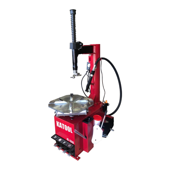
Tire Changer KT-830 User’s Manual Equipment description 2.1 Product introduction This model of semi-automatic tire changer is a convenient and quick disassemble and installation of wheel size of 10” to 28”, the tire width of 110-380mm and the diameter of the tire is 1040mm. - Page 11 Tire Changer KT-830 User’s Manual 2.4 Figure and part name G:Wheel Clamp P:Tower U:Bead Breaker Pedal I:Mounting / Dismounting head R:Bead Breaker V2:Turntable Pedal V3: Pedal Inflatable Z: Bead Breaker Pad Y: Turntable N: Horizontal Pendulum arm...
- Page 12 Tire Changer KT-830 User’s Manual K: Locking Handle Q: Oil Drier V1: Wheel Clamp Pedal C: Turbo Blast Hose Assembly E: Hand Wheel M: Vertical Reverse Spring...
- Page 13 Tire Changer KT-830 User’s Manual...
-
Page 14: Installation And Commissioning Instructions
Tire Changer KT-830 User’s Manual Installation and commissioning instructions 3.1 Installation Preparation 3.1.1 installation location The area should provide the operator with enough space to use the equipment in a safe manner. ⚫ The area selected should be well lit, easy to clean and should be away from oil, grease, brake lathe ⚫... -
Page 15: Precautions During Installation
Tire Changer KT-830 User’s Manual 3.1.2 Installation equipment and tools ◇ Installation equipment and tools 3.1.3 inspection products ◇ The shipment should be thoroughly inspected as soon as it is received. The signed Bill of Lading is acknowledgement by the shipping carrier as receipt of this product as listed in your invoice as being in a good condition of shipment. -
Page 16: Main Installation Procedure
Tire Changer KT-830 User’s Manual 3.3 Main installation procedure 3.3.1 Standard configuration installation ◆ The first step: unscrew wooden pallet fixing screws, tire changer placed at the installation site. (installation site must conform to the requirements. ◆ The second step: unscrewing the bolts from the box, the column is installed in the machine box on the specified position, tighten the bolts. -
Page 17: Check The Project Table After Installation
Tire Changer KT-830 User’s Manual 3.4 Check the project table after installation Inspection item Remarks Whether the power supply voltage is consistent with the requirements of the equipment Whether the components are installed correctly Whether the bolts, screws, nuts are tightened Note: Please fill in the inspection item list after the installation is finished. -
Page 18: Operation
Tire Changer KT-830 User’s Manual ◇ The forth step: Swing Arm / Vertical Shaft / Mount-Demount Head Assembly ⚫ Raise the Vertical Shaft / Mount-demount head assembly to the highest position and lock it in place by pushing the Locking Handle up. - Page 19 Tire Changer KT-830 User’s Manual that the valve stem is either in the 12 o’clock or 6 o’clock position. ◇ Position the bead breaker blade against the tire next to, but not on, the rim or the sidewall of the tire. Press the breaker pedal to actuate the blade and loosen the bead. It may be necessary to loosen the bead in multiple locations around the tire.
- Page 20 Tire Changer KT-830 User’s Manual ◇ Use the Wheel Clamp Foot Pedal to move the Clamps inward (pedal down) or outward (pedal up). 4.2.3 Tire mounting ◇ Apply tire manufacturer’s approved rubber lubricant liberally to entire circumference of both upper and lower beads after loosening bead and placing on table top. ◇...
- Page 21 Tire Changer KT-830 User’s Manual ◇ Pull the locking handle towards you to lock the Vertical Shaft into position. As the slide is locked, the Mount/ Demount Head will move upward approximately 1/8 inch and backward 1/8 inch from the rim edge. The Mount/Demount head roller should not be in contact with the rim edge.
- Page 22 Tire Changer KT-830 User’s Manual THE BEAD LIFTING TOOL AND DEMOUNT HEAD MAY ENCOUNTER RESISTANCE OR COME UNDER LOAD AT TIMES DURING THE MOUNT AND DEMOUNT PROCEDURES. KEEP ONE HAND FIRMLY ON THE TOOL TO AVOID POSSIBLE TOOL KICK BACK. USE THE REVERSING FEATURE (LIFT TABLE TOP PEDAL UPWARDS) TO BACK OUT OF JAM UPS.
- Page 23 Tire Changer KT-830 User’s Manual ◇ Depress the Table Top Pedal to rotate the wheel ◇ The Mount / Demount Head will guide the bead up and over the edge of the wheel. Continue rotation until the lower bead is demount. CUSTOM AND SPECIAL WHEELS IF A CUSTOM WHEEL IS DAMAGED WHILE DEMOUNTING, STOP, AND AVOID DAMAGING THE OTHER WHEELS.
-
Page 24: Mounting
Tire Changer KT-830 User’s Manual WHEELS WITH TIRE PRESSURE WARNING SENSORS ◇ After both tire beads are loosened, try to remove the tube. If you cannot remove the tube lubricate the beads and rim liberally DEMOUNTING TUBE TYPE TIRES 4.2.4 Demount Tube type tires ◇... - Page 25 Tire Changer KT-830 User’s Manual tire and wheel. ◇ Lubricate both tire beads liberally with tire manufacturer’s approved lubricant. THE RIM AND BEAD MUST BE LIBERALLY LUBRICATED. FAILURE TO USE AN ADEQUATE LUBRICANT CAN LEAD TO THE BEAD BINDING ON THE RIM AND LEAD TO DAMAGE TO THE MOTOR AND OR VOID THE WARRANTY.
- Page 26 Tire Changer KT-830 User’s Manual IF YOU DAMAGE THE TIRE BEAD DURING MOUNTING, STOP! REMOVE THE TIRE AND MARK IT AS DAMAGED. DO NOT MOUNT A DAMAGED TIRE. ◇ Place tire over wheel and move Vertical Arm and Mount/ Demount Head into position as described earlier.
- Page 27 Tire Changer KT-830 User’s Manual DO NOT FORCE THE TIRE ONTO THE RIM. BEAD DAMAGE COULD RESULT MAKING THE TIRE UNSAFE AND/OR CREATING THE RISK OF INJURY. MOUNTING TUBE TYPE TIRES ◇ Lubricate the beads and rim liberally. ◇ Position the Mount/Demount Head as described earlier. Mount the bottom bead first. ◇...
- Page 28 Tire Changer KT-830 User’s Manual INFLATION Review the following descriptions and diagrams carefully. Refer to them as necessary during wheel restraint, bead sealing, bead seating, and inflation to verify that you are proceeding properly and safely. CHECK INFLATION GAUGE FOR PROPER OPERATION. ACCURATE PRESSURE READINGS ARE IMPORTANT TO SAFE TIRE INFLATION.
- Page 29 Tire Changer KT-830 User’s Manual ◇ Tire Inflation - With the Inflation Hose attached to the tire valve and the pedal depressed, line pressure is allowed to flow through the valve and into the tire for inflation. Tire pressure is not indicated on the gauge in this position CHECK THE FUNCTION OF THE PRESSURE LIMITER REGULARLY.
- Page 30 Tire Changer KT-830 User’s Manual Stage of Inflation THIS MACHINE IS NOT INTENDED TO BE A RESTRAINING DEVICE FOR EXPLODING TIRES, TUBES, OR RIMS. KEEP HANDS AND BODY CLEAR AT ALL TIMES AND AS FAR BACK AS POSSIBLE DURING INFLATION. DO NOT LEAN OVER THE TIRE WHILE INFLATING.
- Page 31 Tire Changer KT-830 User’s Manual TO SEAL LOW PROFILE OR DIFFICULT BEADS, USE THE TURBO NEVER POINT NOZZLE TOWARDS YOURSELF OR OTHER PERSONS. INSPECT NOZZLE, TIRE AND WHEEL FOR DEBRIS. NOZZLE MUST BE POINTED TOWARD TIRE BEAD AREA. HOLD NOZZLE SECURELY WITH BOTH HANDS AT ALL TIMES.
- Page 32 Tire Changer KT-830 User’s Manual ◇ Depress inflation pedal and open the Turbo-Blast Valve for less than one full second. The blast of air from the Turbo Blat Nozzle will expand tire and seal the beads. ◇ Repeat these steps if beads have not sealed. It will be necessary to wait a few seconds for the air storage tank to recover before attempting again.
- Page 33 Tire Changer KT-830 User’s Manual NEVER ATTEMPT TO MOUNT AND INFLATE MISMATCHED TIRES AND WHEELS. MISMATCHED TIRE AND WHEEL COMBINATIONS CAN EXPLODE, CAUSING PERSONAL INJURY OR DEATH TO OPERATOR AND BYSTANDERS. FOR SAFETY, DO NOT ATTEMPT TO MOUNT AND INFLATE MISMATCHED TIRES AND WHEELS. CHECK TIRE PRESSURE FREQUENTLY.
- Page 34 Tire Changer KT-830 User’s Manual from the tire by pressing the manual Pressure Relief Valve NOTE: WHEN INFLATING TIRES THAT REQUIRE MORE THAN 60 PSI, ALWAYS USE A SAFETY CAGE AND AIR HOSE WITH A CLIP-ON AIR CHUCK AND IN-LINE VALVE. THE HOSE MUST HAVE ENOUGH LENGTH BETWEEN THE CHUCK AND THE OPERATION/IN-LINE VALVE TO ALLOW THE TECHNICIAN TO STAND OUTSIDE THE TRAJECTORY...
-
Page 35: Maintenance
Tire Changer KT-830 User’s Manual WEAR PROTECTIVE CLOTHING AND USE EYE PROTECTION WHEN MAKING ANY ADJUSTMENTS Maintenance OR REPAIRS TO THE MACHINE. 5.1.1 Maintenance ◇ Prohibit unauthorized personnel for maintenance operation. To extend the service life of the tire changer, maintenance should be performed according to the requirements of the manual. - Page 36 Tire Changer KT-830 User’s Manual ◇ As shown in figure 15-c, machine horsepower is not enough, check the triangle belt of the motor by the following steps: (before any operation, to cut off the power) first, Unscrew the 4 screws on the side of the box, remove the left side protective plate of the tire changer, second, use special adjustment screw X (Figure 15-c) that is in the motor support base to adjust the triangle belt.
- Page 37 Tire Changer KT-830 User’s Manual Figure 15-b Figure 15-a Figure 15-e Figure 15-d Figure 15-c...
-
Page 38: Storage And Scrap
Tire Changer KT-830 User’s Manual 5.2 Storage and scrap 5.2.1 Storage ◇ If you want a long-time storage of machine, please disconnect all the energy supply, and lubricate the skidway of the clamps on the turntable to prevent oxidation. 5.2.2 Scrap In accordance with the law of the metal and nonmetal for scrap processing. - Page 39 Tire Changer KT-830 User’s Manual the rim correctly Replace cylinder repair Rotary cylinder has trouble cylinder sealing ring Lock plate adjustment is not Adjust or replace the locking correct or faulty plate (Figure 18/d) Working head can touch the rim Working head screw loose Tighten screws (Figure 12/a) The pedal is not located...
-
Page 40: Parts List And Exploded Drawings
Tire Changer KT-830 User’s Manual Parts List and Exploded Drawings... - Page 41 Tire Changer KT-830 User’s Manual 88013000 Box Weld 620+310A Tower Weld 6206000 Turntable ASSY 6207000 Gear Box ASSY 8808000 Pedals ASSY 8805100 Φ200 Aluminum Cylinder Unit 8805200 Φ200 Aluminum Cylinder piston 5804000 Universal Blade Weld 620B420 Bead Breaker Weld 5704200 Inflation Box Unit 8803000 Horizontal Arm Unit...
-
Page 42: Warranty
Tire Changer KT-830 User’s Manual LIMITED WARRANTY Lenox® Wheel Service Equipment is warranted for the period of one year on all operating components to be free of defects in material and workmanship. Lenox® shall repair or replace at their option for the warranty period those parts returned to the factory freight prepaid which prove upon inspection to be defective.
Need help?
Do you have a question about the KT-810 and is the answer not in the manual?
Questions and answers