Table of Contents
Advertisement
Quick Links
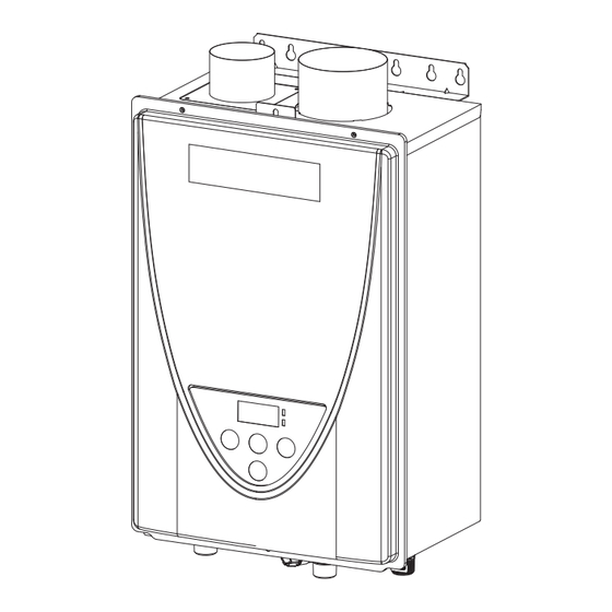
Hydro Smart 115 PLUS Gas Micro Boiler
Installation Manual and Owner's Guide
Hydro Smart 115
The
Micro Boiler is a compact and powerful
residential unit with a versatile BTU
modulating range.
Featuring
•
Flow Activated: .75 GPM
•
Wall Hung
•
Copper Heat Exchanger
•
Temperature Range: 99°-140° F
•
Freeze Protection
•
Power Vent
•
CAT III Stainless Steel Venting
•
Built in Boiler Remote
•
Includes LP Conversion Kit
Boiler is set up for
PLUS Gas
NG/LP
NG, includes LP
Conversion Kit
Do not return to stores. Damages or
repairs call Hydro Smart 763-331-3066
M-F 8 AM - 5 PM
If the information in these instructions is not
followed exactly, a fire or explosion may result
causing property damage, personal injury or
death.
-Do not store or use gasoline or other flammable
vapors and liquids in the vicinity of this or any
other appliance.
-WHAT TO DO IF YOU SMELL GAS
•
Do not try to light any appliance
•
Do not touch any electric switch, do not use
any phone in your building.
•
Immediately call your gas supplier from a
neighbor's phone. Follow the gas supplier's
instructions.
•
If you cannot reach your gas supplier, call the
fire department.
-Installation and service must be performed by
a qualified installer, service agency or the gas
supplier.
If you have any questions,
please call or write to:
10725 165th Ave. NW
Elk River, MN 55331
Sat 8 AM - Noon
Advertisement
Table of Contents

Summary of Contents for Hydro Smart 115 PLUS
- Page 1 Hydro Smart 115 PLUS Gas Micro Boiler Installation Manual and Owner’s Guide NG/LP Boiler is set up for NG, includes LP Conversion Kit Do not return to stores. Damages or repairs call Hydro Smart 763-331-3066 M-F 8 AM - 5 PM...
-
Page 2: Table Of Contents
CONTENTS Installation Manual/Owners Guide SPECIFICATIONS....................4 INTRODUCTION....................5 SAFETY GUIDELINES..................6 INSTALLATION (GENERAL)................7 CLEARANCES....................9 HIGH ALTITUDE INSTALLATIONS..............10 VENTING INSTRUCTIONS (GENERAL)............11 GAS SUPPLY & PIPE SIZE................13 PRESSURE RELIEF VALVE/ELECTRICAL CONNECTIONS......15 APPLICATIONS....................16 INITIAL OPERATION..................18 OPERATING SAFETY..................19 NORMAL OPERATION..................21 TEMPERATURE SETTINGS................22 FLOW/FREEZE PROTECTION................24 MAINTENANCE AND SERVICE...............25 ADDITIONAL FEATURES.................26 VENTING AND CLEARANCES................27 ERROR CODES....................37... -
Page 3: Installation Manual/Owners Guide
Installation Manual & Owners Guide CONGRATULATIONS Congratulations and thank you for choosing our micro boiler. Before use, we recommend that you read through this installation manual carefully. Keep this manual for future reference. If you need an additional manual, contact the manufacturer or your local distributor. -
Page 4: Specifications
*When using boiler in-conjunction with Hydro Smart Combi panel, system pressure may be much higher on your domestic water side. Your space heating side should still reflect the recommended 18-25 PSI for system pressure. -
Page 5: Introduction
INTRODUCTION • This manual provides information necessary for the installation, operation, and maintenance of the boiler. • The model description is listed on the rating plate which is attached to the side panel of the boiler. • Please read all instructions completely before installing this product. •... -
Page 6: Safety Guidelines
SAFETY GUIDELINES SAFETY DEFINITION Indicates an imminently hazardous situation which, if not avoided, will result in death or serious injury. DANGER Indicates an imminently hazardous situation which, if not avoided, could result in death or serious injury. WARNING Indicates an imminently hazardous situation which, if not avoided, could result in minor or moderate injury. -
Page 7: Installation (General)
INSTALLATION GENERAL 1. Follow all local codes, or in the absence of local codes, follow the current edition of the National Fuel Gas Code: ANSI Z223.1/NFPA 54 in the USA or B149.1 Natural Gas and Propane Installation Code in Canada. 2. - Page 8 • Installation and service must be performed by a qualified installer (for example, a licensed plumber or gas fitter). Otherwise, the warranty will be void. • The installer (licensed professional) is responsible for the correct installation of WARNING the boiler and for compliance with all national, state / provincial, and local codes.
-
Page 9: Clearances
CLEARANCES Back Side Front Side Model Bottom Front Back Sides 12 in. 12 in. 4 in.** 1.0 in. 3 in. HS115 PLUS (NG/LP) (305 mm) (305 mm) (102 mm) (25 mm) (76 mm) **24 inches recommended for maintenance. Installation LP Conversion Kit Manual Manifold gasket: 1 Qty: 1... -
Page 10: High Altitude Installations
HIGH-ALTITUDE INSTALLATIONS Check the elevation where your boiler is installed. Set your DIP switches according to altitude as shown below. DIP Switch Settings 2,001 to 3,001 to 5,001 to 7,501 to Altitude 0 to 2,000 ft. 3,000 ft. 5,000 ft. 7,500 ft. -
Page 11: Venting Instructions (General)
VENTING INSTRUCTIONS For indoor models -General- • Improper venting of this appliance can result in excessive levels of carbon monoxide which can result in severe personal injury or death. • Improper installation can cause nausea or asphyxiation, severe injury or death from carbon monoxide and flue gases poisoning. - Page 12 • A condensate collector is required for horizontal and/or vertical vent runs exceeding 5 ft. of equivalent length (not including sidewall terminatons). • A backflow preventor should be installed in the exhaust when the heater is installed in climates subject to freezing temperatures. General rules for vent terminations: •...
-
Page 13: Gas Supply & Pipe Size
GAS SUPPLY AND GAS PIPE SIZING -General- • Do not use this boiler with any gas other than the one listed on the rating plate unless the boiler has been properly converted. • Ensure that any and all gas regulators used are operating properly and providing gas pressures within the specified range shown below. - Page 14 -Natural Gas Supply Piping- Maximum delivery Capacity of Cubic Feet of Gas per Hour of IPS Pipe carrying Natural Gas with 0.60 Specific Gravity Based on Pressure Drop of 0.5" W.C. Based on Energy Content of 1,000 BTU/Cubic ft.: The boiler requires 140 Cubic ft./hr. The following tables are from NFPA 54 Unit: Cubic feet per hour Pipe Size...
-
Page 15: Pressure Relief Valve/Electrical Connections
OFF and call a qualified person to determine the cause. • No valve shall be placed between the relief valve and the water heater. NOTE: Hydro Smart Radiant Panel systems include a pressure relief valve for the radiant application. ELECTRICAL CONNECTIONS •... -
Page 16: Applications
Hydro Smart pre-plumbed panels help make space heating easy and reliable. These panels are professionally engineered and use proven Primary/Secondary hydronic practices. Call Tech Support (1-763-331-3066) for assistance. Sample: HSPS120LT 1 Zone Panel: For more information on Hydro Smart pre-plumbed panels and zoning options for this boiler please visit www.hydro-smart.com or call 763-331-3066. - Page 17 Dual-purpose hot water heating (Domestic and Space Heating) Insert a Hydro Smart Combi Panel to provide potable heated water and Hydronic Heating (with space heating panel(s)) with one heat source. The Hydro Smart Combi Panel integrates with a wide variety of boilers and delivers “Priority” potable heated water with no storage tank and hydronic space heating in a small reliable package.
-
Page 18: Initial Operation
INITIAL OPERATION FOR YOUR SAFETY, READ BEFORE OPERATING • Check the GAS and WATER CONNECTIONS for leaks before firing the unit for the first time. • Open the main gas supply valve to the unit using only your hand to avoid any spark. Never use tools. -
Page 19: Operating Safety
OPERATING SAFETY FOR YOUR SAFETY READ BEFORE OPERATING WARNING: causing property damage, personal injury or loss of life. A. This appliance does not have a pilot. It is equipped with an ignition device which automatically lights the burner. Do not try to light the burner by hand. B. - Page 20 DANGER area near the water heater. used will reduce, but not eliminate the risk of vapors being ignited by the main burner. Flammable Vapors FLAMMABLES Read and follow water heater warnings and instructions. If the owner’s manual is missing, contact the retailer or manufacturer. Vapors: Far away from heater.
-
Page 21: Normal Operation
NORMAL OPERATION BUILT-IN CONTROLLER and REMOTE CONTROLLER from examples. Built-In controller Built-in controller Remote controller Display for Temperature "INFO" Button When the STAND BY LED is ON, the hot water temperature will be Each time the button is pressed, displayed. the operation mode is selected in the sequence of the following. -
Page 22: Temperature Settings
TEMPERATURE SETTINGS -Set temperature- Screen on the controller Operation Built-in controller Remote controller Turn on the 120 VAC power supply to the unit. Press the "ON/OFF" button on the controller in order to turn the controller on. When ON, the STAND BY LED is lit. It shows the set temperature on its display as shown in (EX.: 120 °F) the picture on the right. - Page 23 TEMPERATURE SETTINGS ON THE PCB WITHOUT CONTROLLER • Turn off the power supply to the boiler before changing the DIP switch settings. WARNING There are two preset temperatures, 120 °F (50 °C) and 140 °F (60 °C), that you can select by changing the DIP switch settings on the computer board without the controller.
-
Page 24: Flow/Freeze Protection
FLOW (DHW Applications) Household Flow Rates The flow rate through the boiler is limited • to a maximum of 6.6 GPM Flow rate Appliance/Use The temperature setting, along with the supply • GPM (US) L/min temperature of the water, will determine the flow Lavatory Faucet rate output of the unit. -
Page 25: Maintenance And Service
MAINTENANCE AND SERVICE Turn off the electrical power supply and close the manual gas shutoff valve and the manual water control valve before servicing. WARNING • Clean the filter (Strainer) on the system. • Be sure that all openings for combustion and ventilation air are not blocked. •... -
Page 26: Additional Features
You can get some information about the boilers condition by pressing the "INFO" button. For more information, follow the procedures below: Screen on the controller INFO Operation Button Built-in controller Remote controller Inlet water temperature will be displayed on 1st. press the remote controller by pressing the "INFO"... -
Page 27: Venting And Clearances
INSIDE CORNER DETAIL Vent terminal Air supply inlet Area where is not permitted Gas meter / regulator Canada U.S.A Direct-vent and other Direct- Other than than Direct-vent vent Direct-vent Clearance above grade, veranda, porch, deck, or bal- 1 foot 1 foot 1 foot (30 cm) (30 cm) - Page 28 -Clearances for For multiple sidewall exhaust terminations (e.g. multi- unit systems), an exhaust termination must be at least 1 ft. (305mm) away from another exhaust termination. An exhaust termination must also be at least 2 ft. (610 mm) away from an inside corner. If the adjacent wall is less than 2 ft.
- Page 29 -Clearances for sidewall terminations- For direct-vent sidewall terminations that use two separate penetrations for the intake and exhaust, comply with the minimum clearances shown in the diagrams below. Exhaust Exhaust Intake Intake <Case 1> 0.4 ft. (130 mm) min. 1 ft. (305 mm) 0.4 ft.
- Page 30 DIP switch settings for direct vent installation HS115 PLUS Vent length No. 6 : O N ON 1 2 3 4 5 6 7 8 9 10 0 to 20 ft. No. 7 : OFF (0 to 6.1 m) No. 8 : OFF 21 to 40 ft.
- Page 31 -DIP Switch Settings for Vent Length- • Improper venting of this appliance can result in excessive levels of carbon monoxide which can result in severe personal injury or death. • Improper installation can cause nausea or asphyxiation, severe injury or death from carbon monoxide and flue gases poisoning. Improper DANGER installation will void product warranty.
- Page 32 -Vent length and No. of Elbows- This is a Category III appliance and must be vented accordingly. The vent system must be sealed airtight. All seams and joints without gaskets must be sealed with high heat resistant silicone sealant or UL listed aluminum adhesive tape having a minimum temperature rating of 350 °F (177 °C).
- Page 33 Gable vent to outdoors Install above 12” maximum Outlet air to Confined 4,000 btu/h Two permanent Openings Confined Alternate 1 in Space Inlet air from Air Inlet 4,000 btu/h 12” maximum 4,000 btu/h Direct to outdoors openings Direct to outdoors openings Two permanent openings 1 in 2,000 btu/h...
- Page 34 • This gas boiler requires an adequate source of clean air for combustion and ventilation. Without sufficient air, your boiler may not operate properly and may emit excessive and abnormal amounts of carbon monoxide which may result in carbon monoxide poisoning or death. WARNING Before installing the boiler, you must determine the amount of air needed to supply this boiler boiler.
- Page 35 Calculate the air volume of the room Air requirements depend on the size of the room. If there are large objects in the room (e.g., refrigerator, furnace, car), subtract their volume from the vol- Air Volume = Room Volume - Object Volume Calculate required air volume A boiler installed in an unconfined attic, garage, or space requires that the space be at least 50 cubic feet per 1,000 BTU/h of the total input for all gas burning appliances in the same area.
- Page 36 Calculate minimum size of vent openings and ducts vents use louvers or grilles to protect the opening. The louver or grill itself blocks some of the free area, so the open- ing may need to be larger to meet the minimum free area requirements. 134 square inch openings if using metal louvers rated at 75% free area (100 sq.
- Page 37 -General- The units have self-diagnostic functions for safety and convenience when troubleshooting. If there is a problem with the installation or the unit, the error code will be displayed on the built-in controller or remote controller. Consult the table on the following pages for the description of each error code. Error code indicator on the built-in controller Error code indicator on...
-
Page 38: Error Codes
-Fault Analysis of Error Codes- If the error code is displayed on the computer board of the boiler or the controller, please check the following. After checking, consult with the manufacturer. Green Malfunction Remote Diagnosis description One Flash Incorrect DIP switch •... - Page 39 Green Malfunction Remote Diagnosis description Six Flashes Abnormal main gas • Check for connection/breakage of wires (Part #708) and/ solenoid valve or burn marks on the computer board (Part #701). Six Flashes Abnormal gas • Check for connection/breakage of wires (Part #714) and/ solenoid valve or burn marks on the computer board (Part #701).
-
Page 40: Troubleshooting
TROUBLESHOOTING GENERAL PROBLEM SOLUTIONS It takes a long time to • The time it takes to deliver hot water from the boiler to your get hot water at the fixtures depends on the length of piping between the two. The longer fixtures. - Page 41 15 to 70 seconds in order to re-ignite quickly, as well operation has stopped. as purge all the exhaust gas out of the flue. Unit sounds abnormal • Contact the Hydro-Smart Inc. PH: 763-331-3066 or by while in operation E-mail: info@hydro-smart.com Built-in and remote •...
-
Page 42: Components Diagram
Components Diagram Case Assembly Built-in Temperature Controller... - Page 43 Water Way Assembly To Water To Water Water inlet section Water outlet section...
- Page 44 Computer board Assembly Surge box Assembly...
- Page 45 Burner Assembly Burner assembly Manifold assembly LP Conversion Kit...
-
Page 46: Parts List
PARTS LIST Part # Item # Description HS115 PLUS Case assembly for Indoor models EK596 Front cover for Indoor models EK598 Bracket EK455 Intake air port assembly EK600 Junction box 319143-510 EK190 Power supply cord assembly 319143-437 EKK4D Back guard panel EK601 Overheat-cut-off... - Page 47 Part # Item # Description HS115 PLUS Burner gasket 319143-568 EK567 Burner holder gasket 319143-569 EK568 Surge box plate 319143-176 EK436 PCB fixing plate EK603 Thermostat 319143-185 EKJ59 LP Conversion kit 100270585 EK604 Manifold gasket 319143-581 EK592 O-ring P18 NBR (Manifold) EK570 O-ring P20 NBR (Black) 319143-057...
-
Page 48: Output Temperature Chart
Part # Item # Description HS115 PLUS Computer board 100270582 EK611 Surge box 320273-128 EK280 120 VAC wire for Indoor models 319143-427 EK146 Switch wire EK614 120 VAC Power ON-OFF switch EK590 Remote controller wire 319143-490 EK189 Gas valve wire EK585 Flame rod wire EK586... -
Page 49: Notes
Boiler Notes:...
Need help?
Do you have a question about the Smart 115 PLUS and is the answer not in the manual?
Questions and answers
How to get the 3” intake collar to pvc
To connect the 3” intake collar of the Hydro Smart 115 PLUS to PVC, install a 3" elbow into the air intake. Ensure that the PVC used is not cellular core PVC, as its use is prohibited. Use solid PVC that complies with ASTM standards for venting.
This answer is automatically generated