Table of Contents
Advertisement
Quick Links
Timekeeper™
TimeKeeper
TM
F-Series Users manual
COPYRIGHT:
2000-2019 (C) by Alzatex, Inc.
This software package is installed on many of the Alzatex TimeKeeper
displays with 0.56" high digits to 36" high digits. The displays may have 1 to 16 digits and may have zero to 24
buttons. All models have remote inputs and/or a serial communication port. Optional remote button modules may be
used to control the timer/display.
Applications
Production Monitoring and Production Control.
Sporting Events of all kinds.
Take-a-number Systems.
Days since last accident display.
Count down clocks.
Public Speaking events.
Master Clock Systems.
And many others.
TM
TMR221B TimeKeeper
display.
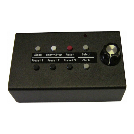
KP215A Remote Keypad with 8 buttons and a knob.
VERSION=5C
Users Manual
with 8 buttons, knob and LED
Page 1 of 33
TM
, products including timers and displays with
KP219A-RF2 wireless keypad with 18 buttons and a
knob.
DSP606S Large LED display on a tripod.
01/11/20
www.alzatex.com
Advertisement
Table of Contents

Summary of Contents for Alzatex Timekeeper F Series
- Page 1 COPYRIGHT: 2000-2019 (C) by Alzatex, Inc. This software package is installed on many of the Alzatex TimeKeeper , products including timers and displays with displays with 0.56” high digits to 36” high digits. The displays may have 1 to 16 digits and may have zero to 24 buttons.
- Page 2 The 8 preset is the power up preset. Remote Display. • This unit can operate as a remote display slave to another Alzatex TimeKeeper , or may be remotely controlled by a computer, Crestron, AMX system or PLC. Take-A-Turn System.
- Page 3 Mode 0: (default) Stop when the timer reaches zero. In this mode, the timer stops when the elapsed time • reaches zero. Mode 1: Red blink on timer zero. The red indicator blinks until the timer is reset. • VERSION=5C Page 3 of 33 www.alzatex.com...
- Page 4 “-lArm.” The current warning time setting will appear. Turn the Knob to the minute(s) setting desired. • Tap the Select” button once and turn the knob to add seconds. • Tap the Reset button to return to the count-down time. • VERSION=5C Page 4 of 33 www.alzatex.com...
- Page 5 DSP602F, DSP604F, DSP606F, DSP608F – Timer with 6” high individual LED digits. • DSP702F, DSP703F, DSP704F, DSP706F, DSP708F – Timer with 7” high individual LED digits. • DSP1002F, DSP1003F, DSP1004F, DSP1005F, DSP1006F, DSP1008F – Timer with 10” high individual • LED digits. VERSION=5C Page 5 of 33 www.alzatex.com...
- Page 6 When two units are connected together, in a specific configuration. Either unit can control all of the functions. Connect the transmit port of the first Timekeeper™ to the receive port of the second Timekeeper™. • VERSION=5C Page 6 of 33 www.alzatex.com...
-
Page 7: Clock Mode
The remote displays are updated once per minute with the correct time of day. Device control Outputs Optional Relay Control signal (BEEP). Activated whenever the timer reaches time zero. Beep relay. • VERSION=5C Page 7 of 33 www.alzatex.com... -
Page 8: Dimming The Display
(default 1). The KP03A or OC002A keypads can be configured to use the inputs you specify. Remove the rear cover of the KP03A or OC002A and configure the jumpers the way you desire. Common configurations. VERSION=5C Page 8 of 33 www.alzatex.com... - Page 9 Activating more than one of the inputs at a time (LEGACY mode) These functions operate in legacy mode only. These functions are disabled if the MSETUP setting is not in legacy mode. VERSION=5C Page 9 of 33 www.alzatex.com...
- Page 10 Press the Select button to advance to the button delay for IN2. The display will show " ". • Turn the Knob to change the selected button delay value. • 3-00 Press the Select button to advance to the button delay for IN3. The display will show " ". • VERSION=5C Page 10 of 33 www.alzatex.com...
-
Page 11: Counter Mode
• Press the select button again. • Turn the knob to set the upper two digits (00xxxx-99xxxx) • Press the select button. • Turn the knob to set the lower two digits (xxxx00-xxxx99) • VERSION=5C Page 11 of 33 www.alzatex.com... -
Page 12: Remote Display Mode
In addition to alphanumeric characters, the seven-segment LED displays are also able to show the dash, space and period characters (“-”, “ “, “.”). Any other characters not mentioned here may be ignored by the display, potentially causing the entire message to be ignored. VERSION=5C Page 12 of 33 www.alzatex.com... -
Page 13: Rear Panel Buttons
Press the Test button again to display the segment test pattern sequence. Observe the display. The segments should light in the sequence as described below. segment a on; segment a-b on; segment a-b-c on; segment a-b-c-d on; segment a-b-c-d-e on; segment a-b-c-d-e-f on; segment a-b-c-d-e-f-g on; segment a-b-c-d-e-f-g-dp on; VERSION=5C Page 13 of 33 www.alzatex.com... - Page 14 50Hz/60Hz Sync signal detected. --63A Example with button pressed. If the display shows “ ”, this indicates that Button 1 is pressed, Remote Input 1 is active and 50Hz/60Hz Sync signal detected. VERSION=5C Page 14 of 33 www.alzatex.com...
-
Page 15: Configuration And Setup
Mode 8: Beep at the warning times. You can add 8 to any of the other modes. Ie: Mode 9 is beep at bb08 the warning times and at zero. Note: See Beeper and relay setup options for additional beep options. (Revision 36) Select the special timer mode VERSION=5C Page 15 of 33 www.alzatex.com... - Page 16 Mode 4: Change the display to the heat number when the timer reaches zero. The heat number is incremented each time the timer reaches zero. If needed, the heat number can be changed by turning the knob. VERSION=5C Page 16 of 33 www.alzatex.com...
-
Page 17: Configuration Settings
The display will show " ". • U..A Wait 2-3 seconds. The display will show " ". • Turn the knob to change the value. • Tap any other button to exit the setup mode. • VERSION=5C Page 17 of 33 www.alzatex.com... - Page 18 DD DD DD DD DD Days u.15 SS SS SS SS SS S.TTT S SS.TTT S.TTT Seconds. Thousandths of a second u.16 NOTE: When mode 15 is selected, the days timer rolls over at midnight. VERSION=5C Page 18 of 33 www.alzatex.com...
- Page 19 Remote input 1 increments hours. Remote input 2 increments minutes. Remote input 3 increments seconds. Used on DSP106B. Remote input 1 is RESET-START if the timer is not already running. If the timer is already running, nothing happens. VERSION=5C Page 19 of 33 www.alzatex.com...
-
Page 20: Beep Enable
The relay/beep output is a Morse code character Select the desired beep tone sequence types. sequence while beeping. The relay output is modulated with a beep tone while The relay/beep output is a pre-programmed beeping. register beep sequence while beeping. VERSION=5C Page 20 of 33 www.alzatex.com... -
Page 21: Unit Address Setup
Example corresponding commands are "L0xxxx through "L9xxxx and "LAxxxx through "LOxxxx. The address range is 0 to 1F in ASCII HEX notation where 0= “L0xxxx; 10=”L@xxxx; 11=”LAxxxx and 1F=”LOxxxx. Example: VERSION=5C Page 21 of 33 www.alzatex.com... - Page 22 To enter the setup mode, press and hold the Start button until the display changes. • The display will show " ". • Tap the Select button several times to advance to the extended unit address setup setting. • VERSION=5C Page 22 of 33 www.alzatex.com...
- Page 23 The display will show " ". • Wait 2-3 seconds. The display will show " ". • Turn the knob to change the value. • Tap any other button to exit the setup mode. • VERSION=5C Page 23 of 33 www.alzatex.com...
- Page 24 AC or receiving a 50/50Hz sync signal, this option has no effect. All received serial data characters are echoed out on the transmit serial port. This unit does not transmit RLY, DSP or “L0 commands. VERSION=5C Page 24 of 33 www.alzatex.com...
-
Page 25: Baud Rate Setup
• 6=56,800 baud. • 7=115,200 baud. • NOTE: Most Alzatex products default to 2,400 baud. The baud rate should be set to " ". in most situations. Default brightness setup Method 1: Use the Test button on the rear of the unit. -
Page 26: Resetting To Factory Default Settings
Release the test button, the reset is successful. • Turn the display off, then ON again. The reset is complete. • If you had some custom settings, you will need to restore any custom settings. • VERSION=5C Page 26 of 33 www.alzatex.com... - Page 27 Using a 6 conductor modular cord, the RJ11-TX is typically used for transmit data on DATA 1 and receive • data on DATA 3. The RJ11-RX connector is typically used for receive data on DATA 1 and transmit data on DATA 3. VERSION=5C Page 27 of 33 www.alzatex.com...
- Page 28 (2) BK Timer Pause IN 1 Pause (3) RD Ground Ground (4) GN Display Reset Timer Reset IN 2 (5) YL — IN 4 (6) BL Use 6P6C Standard Modular Cord with LED displays. VERSION=5C Page 28 of 33 www.alzatex.com...
- Page 29 Pairs 2,3,4 (Orange/White, Green/White and Brown/White) are used to carry 12VDC power. • In some cases, Pair 2 (Green/White) are used for data in the reverse direction. These units have special • configuration jumpers to change the function of pair 2. VERSION=5C Page 29 of 33 www.alzatex.com...
-
Page 30: Wireless Communication
Keep in mind that larger displays require more power. The power supplies within a display unit has specific limitations. DO NOT overload the power supply. If you are powering a larger number of displays, Alzatex provides a KT6X422A or KT8X422A distribution module that permits multiple displays to be powered from a single source. - Page 31 In this mode the clock is the most accurate. The clock is as accurate as the AC line frequency. In most • countries the accuracy is within five seconds per year. Timekeeper™ wiring diagram examples are available in separate documents. See the specific application note that best fits your application. VERSION=5C Page 31 of 33 www.alzatex.com...
-
Page 32: Revision History
If the timer is already running, the button press is ignored. Added a feature to DSP104B so that the 6 buttons operate as a timer with BTN1=run/pause, BTN2-Reset, • BTN3=Recall, BTN4=Mode, BTN5=Increment minutes, BTN6=Increment seconds. VERSION=5C Page 32 of 33 www.alzatex.com... - Page 33 Added an additional test to the 32KHZ oscillator. This test verifies that it is actually running at the correct • frequency. Errors are sent to serial port 1. Version 5C. Added a feature to reset the factory default settings. • VERSION=5C Page 33 of 33 www.alzatex.com...
Need help?
Do you have a question about the Timekeeper F Series and is the answer not in the manual?
Questions and answers