Table of Contents
Advertisement
Quick Links
Advertisement
Table of Contents

Related Manuals for Embention Veronte PCS

Summary of Contents for Embention Veronte PCS
- Page 1 Veronte PCS Embention Apr 21, 2022...
-
Page 3: Table Of Contents
CONTENTS 1 Technical Features ..........Mechanical Specifications . -
Page 5: Technical
CHAPTER TECHNICAL 1.1 Features • Ready for operation • Compatible with Veronte MCS or third party computers • RTK & differential barometer base • Wifi, Ethernet and USB communications • Expansion bay (free space for customer electronics installations) • Easy maintenance •... -
Page 6: Electrical Specifications
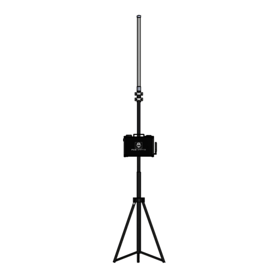
Veronte PCS 1.3 Electrical Specifications PCS DC input 14 to 24 VDC PCS power 30W to 80W (depending on version) Power supply 180-264 VAC 50-60 Hz input Battery type LiFePO4 Battery capacity 10 Ah Battery operation 2 hours typically (depending on version) - Page 7 Veronte PCS Fig. 1: Product Components - Interface dimensions Veronte PCS is supplied together with a telescopic foldable mast that can be extended up to 3m. Next you can find the maximum and the minimum dimensions of the system when installed.
- Page 8 Veronte PCS Fig. 2: System Dimensions Chapter 1. Technical...
-
Page 9: Versions
Versions with main specifications are described below. Variant name Frequency Amplifier R F Frequency Video Antenna Power hopping type Veronte PCS Control Station (w/o Datalink) V2.0 No Radio Radio Radio Radio antenna Veronte PCS Control Station (Datalink DT 2.4GHz 2.4GHz Yes 15dBi - 5W - Video &... -
Page 10: Interfaces
Veronte PCS 1.6 Interfaces Fig. 4: PCS Interfaces - Parts identification Chapter 1. Technical... - Page 11 Veronte PCS Fig. 5: PCS Interfaces - Parts identification 1.6. Interfaces...
- Page 12 Veronte PCS Fig. 6: PCS Interfaces - Parts identification Items PCS Harness connector Integrated GNSS antenna RF 1 antenna (SMA female) RF 2 antenna (SMA female) GNSS 2 antenna (SMA female) Connector for Expansion Bay Ethernet connector Wifi antenna connector (SMA female RP)
-
Page 13: Part List
Veronte PCS 1.7 Part list The system consist of a multiple components listed below. Quantity Items Veronte PCS Control Station Unit Pole and wall mounting accessories Foldable mast Connection harness Veronte Control station Power source (euro plug) 5m ethernet extension cable... - Page 14 Veronte PCS Chapter 1. Technical...
-
Page 15: Installation
• Only one dhcp device connection can be done simultaneously. If more than one is meant to be connected, then it is needed to configure a Static IP, as established in Operation section. • Veronte PCS is IP54 protected while closed. However, it loses its water resistance meanwhile the outer cover is open. -
Page 16: Basic Connection Diagram
Veronte PCS 2.2 Basic Connection Diagram Fig. 1: Basic Connection Diagram 2.3 Pinout PCS Harness connector The 68 pin main connector has the distribution of input/output channels as follows: Chapter 2. Installation... - Page 17 Veronte PCS PCS Unit - Input pins Pin nº Function Pin nº Function Pin nº Function Pin nº Function PWM 1 RS-485_RX- PWM 2 RS-232 TX RS-485_RX+ PWM 3 RS-232 RX RS-485_GND PWM 4 Ethernet Tx+ (*) ANALOG_1 Not used (*)
- Page 18 Veronte PCS PCS Unit - Output pins Pin nº Function Pin nº Function 3.3V (Output) Not used (*) Not used (*) 5V (Output) Not used (*) Not used (*) 12V (Output) CANA_P RS232-TX 24V (Output) CANA_N RS232-RX Warning: RS-232 pins are common with the external pinnout.
-
Page 19: Mechanical Installation
HI-J35S-Screw-F Power source PT06A-10-6S(005) 2.4 Mechanical installation There are 2 separate accessories for the Veronte PCS in order to mount the unit on a mast or on the Veronte Tracker or a wall. The accessories are : Pole Mount. Fig. 2: Pole mount Wall Mount 2.4. - Page 20 Veronte PCS Fig. 3: Wall mount The installation of the wall mount is described in the Veronte Tracker Manual. Pole mount installation The pole mount is composed by two aluminun brackets to assemble the PCS to the foldable mast. To assemble the system follow the next steps: 1.
- Page 21 Veronte PCS Fig. 4: Bracket Fixation 2. Introduce the PCS Control Station into the mast and fix it with the two wing bolts. 2.4. Mechanical installation...
- Page 22 Veronte PCS Fig. 5: PCS to pole fixation 3. Fix the antenna to the mast with 13mm open wrench. Chapter 2. Installation...
- Page 23 Veronte PCS Fig. 6: Antenna Fixation 4. Connect the Antenna to the PCS Control Station (N-Male to SMA cable). 2.4. Mechanical installation...
- Page 24 Veronte PCS Chapter 2. Installation...
-
Page 25: Operation
Important: In order to do not to stress the battery unnecessarily, do not forget to turn off the system after use. 3.2 Battery Charge The Veronte PCS can be connected and disconnected from the power supply during the operation without turning off the system. In case of external power supply desconnection, the smart battery managment system will switch automatically from external power supply to the internal battery. -
Page 26: How To Operate
2.4GHz if interferences are noticed. • First of all, a connection between the Control Station (Veronte MCS, Computer, etc) and the Veronte PCS is needed. For that the two available options are Wi-Fi or Ethernet. If connecting through Ethernet, step 2 does not apply. -
Page 27: Joystick Connection
Veronte PCS Fig. 2: How to operate - Ethernet Setup With this, Veronte shall appear connected. If not, refer to the Troubleshooting section (4.1). 3.3.2 Joystick Connection Joystick connection is preconfigured on the main external connector (Pin 55 - EQEP_A – CAP 1). Wireless joystick connection is also possible with the installation of a joystick receiver on the Expansion Bay. -
Page 28: Tracking Antenna Connection
Veronte PCS 3.3.3 Tracking Antenna Connection PWM 1 and 2 are pre-configured to be used with a Tracker Antenna. This does not disable them for different applications (consider a proper configuration might be needed). 3.3.4 Ethernet Internal Device Connection PCS bay has an Ethernet connection fully isolated from the external connector. It is normally used for interconnection with video RF links. - Page 29 Veronte PCS Fig. 4: How to operate - Static IP Configuration 2. If after all these steps it cannot be configured, send an email to support@embention.com 3.3. How to operate...
-
Page 30: Advanced Wi-Fi Configuration
Veronte PCS 3.4 Advanced Wi-Fi Configuration 1. Open a browser and introduce the following address on the search bar: 192.168.8.1 2. The user name is “admin” and the password is “admin01”. For being able to Access this menu, you need to have your unit linked. -
Page 31: Maintenance
If battery needs to be replaced you can ask us for a replacement or buy directly to the supplier (AIRBATT Energiepower, internal number 8000910). Battery replacement will void warranty, please contact Embention first. To extract the battery please follow next steps:... - Page 32 Veronte PCS Fig. 1: Remove screws and cups 2. Unscrew the 4 screws with a 2mm allen crew driver and remove the protective plate. Chapter 4. Maintenance...
- Page 33 Veronte PCS Fig. 2: Remove screws and protective plate 3. Unscrew the 2 screws with a 2mm allen screw driver and remove the battery holder bar. 4.2. Corrective Maintenance...
-
Page 34: Contact Data
5. To close the device make the same steps in a reverse way. Use Loctite 243 to fix all screws and apply 1Nm torque. 4.3 Contact data You can contact Embention in any moment if you need further help and support from the acquired products. You can do that through email, telephone or by visiting our office. - Page 35 Veronte PCS combines perfectly with the Veronte MCS control station. This setup permits the installation of the Veronte PCS init (installing the datalink and sensors) in the open field, maximizing the performance of the GNSS receivers and the datalinks, at the time that the operator can operate from a protected location from the Veronte MCS.
- Page 36 Veronte PCS Fig. 4: Basic Features - Veronte PCS Chapter 4. Maintenance...
- Page 37 Veronte PCS Veronte PCS is ready to be used with a Ground configuration, all sensors and devices integrated and the required wires to connect it to any other Veronte device (tracker, MCS. . . ) The main applications that can be develop with this system are: •...
Need help?
Do you have a question about the Veronte PCS and is the answer not in the manual?
Questions and answers