Table of Contents
Advertisement
Quick Links
Advertisement
Table of Contents

Summary of Contents for inDESIGN MMP-1
-
Page 2: Table Of Contents
CAT6A twisted pair cabling. INSTALL INSTRUCTIONS 4 The MMP-1 is the right choice for users who wish to install FRONT PANEL multiple streaming receivers within close vicinity to one another. With a few simple steps users are able to rename the BT ID to REAR PANEL differentiate installed MMP-1’s throughout buildings such as... -
Page 3: Important Safety Instructions
They can take this product for environmental-safe recycling. WARNING: There are no user serviceable parts inside. Refer all servicing to qualified service personnel. MMP-1: INSTALLATION & OPERATION MANUAL PAGE 3... -
Page 4: In The Box
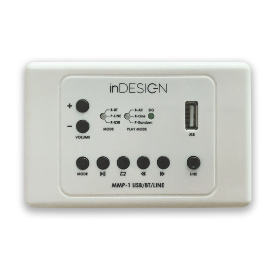
1x The manual you are reading INSTALLING YOUR MMP-1 Mounting your MMP-1 control panel is very easy. The MMP-1’s plastic fascia is based on Clipsal 2000 style mountings. The MMP-1 is compatible with all Clipsal 2000 style mounting accessories, such as C-Clips and standoff boxes. - Page 5 5. Play mode button : This button allows the user to select playback mode of the USB drive when the MMP-1 is in USB playback mode. As this button is pressed the Play Mode LED will cycle Blue, Red or Pink in colour.
-
Page 6: Rear Panel
1. USB: The USB port allows users to plug USB thumb drives into the MMP-1. To playback music files from a USB drive place, the MMP-1 into USB playback mode via the MODE button. *Note: USB drive must be formatted as FAT32. - Page 7 BT Custom Naming In situations where a user has multiple MMP-1 products in close vicinity of each other or the user wishes to change the BT ID of an MMP-1, this can be easily achieved by following the below instructions.
-
Page 8: Connections
The MMP-1 can be connected in different ways to various audio devices. Please note the MMP-1 is designed to work using only one output connection at a time. Please see page 9. *Note: Connecting multiple inputs and outputs and the same time could cause damage to the MMP-1, or other connected equipment. - Page 9 3. RJ45-LAN-XLR Male Patch Cable (included) 4. Balanced line input of a mixer, mixer amplifier, amplifier or powered speaker *Note: in this configuration the balanced line output on the rear of the MMP-1 should not be used. POE Power and Audio via Tail connection This connection method allows users to power the MMP-1 via the PoE power supply over network cable and use the balanced LINE output on the rear panel to connect to a local (in room) balanced line input.
-
Page 10: Specifications
MMP-1 to. 1. RJ45 to RJ45 shielded connectors. Use CAT6A network cable. Max length 100m 2. inDESIGN InLINK Port *Note: in this configuration the balanced line output on the rear of the MMP-1 should not be used. SPECIFICATIONS Product Mounting... -
Page 11: Warranty Info
The Warranty offered by NAS is not transferable. The Warranty will only apply if your NAS product has been installed and used in accordance with NAS’s recommendations as noted in the operating instructions. MMP-1: INSTALLATION & OPERATION MANUAL PAGE 11... - Page 12 The Warranty excludes accessories and consumable goods which have ceased working through normal wear and tear such as, but not limited to, batteries, lamps and other parts classifiable as a consumable part. This includes the CD mechanism and laser fitted to the inDESIGN iDCDP-110. These parts carry a 3 month warranty.
Need help?
Do you have a question about the MMP-1 and is the answer not in the manual?
Questions and answers