
Summary of Contents for Rosco Laboratories X-Effects
-
Page 1: Table Of Contents
Introduction Modules Base Unit Wheel Module Lens Module Analog Control Panel Preparing for Use Assembling the Modules Installing the Lamp (Base Unit) Installing a Glass Pattern (Wheel Module) Installing a Lens Barrel (Lens Accessory) Unit Operation (Analog, Wheel, Lens) Mounting Powering Up Adjusting Brightness Adjusting Focus... -
Page 2: Introduction
Introduction Congratulations on your purchase of the Rosco Laboratories X-Effects 3-D Projector. This modular projector is intended to provide a range of unique lighting effects with high brightness and in a compact package. With the wheel module, these effects include, but are not limited to, light reflecting off water and fire of varying intensities. -
Page 3: Modules
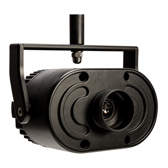
Modules Base Unit The base unit contains the lamp, electronic ballast, first-stage optics, and accessory power supply. The yoke attaches to the side of the base unit in slots for positional adjustment. It also has a slot for special optical filters. Note: When handling the base unit alone, be careful of the front lens, which extends slightly beyond the front plate and is subject to being scratched. - Page 4 Power Control Switch Panel Back View Line Connection Lamp Indicator Special Optics Slot Lamp Lamp Lamp Clip Top View (Lid Removed)
-
Page 5: Wheel Module
Wheel Module The wheel module is made up of motors for rotating two overlapping patterns. It also has shutters and a slot for placing an E-size gobo. Motor Top Lid Alignment Pin Connector Back View Bottom Lid... - Page 6 Front View Top Shutter Gobo Mount Side Side Bottom Shutter Shutter Shutter Glass Pattern Drive Pulley Pull Front View Idle Wheel (with wheels)
-
Page 7: Lens Module
Lens Module The lens module provides the mounting for the various lens barrels. At this time, there are barrels available in 19º, 30º, 50º, and 70º beam angles. It provides screw focusing and a lockdown knob. The lens barrels themselves also have a slot for inserting a dichroic filter. Cover Lock Ring Plastic Cover... - Page 8 Barrel Dichroic Glass Ring...
-
Page 9: Analog Control Panel
Analog Control Panel The analog control panel has all of the panel controls and electronics for controlling the dual-wheel module and controlling the electronic dimming of the lamp. Control Power Indicator Speed Mode Switch Speed Adjustment Brightness Adjust... -
Page 10: Preparing For Use
Preparing for Use Assembling the Modules 1. Unplug the unit. 2. [Optional] Install patterns and lens barrels as desired. 3. Place the base unit such that the front is facing you. 4. Take the wheel module and hold it such that the alignment pins are facing the front of the base unit. -
Page 11: Installing The Lamp (Base Unit)
Installing the Lamp (Base Unit) 1. Unplug the unit. 2. Open the hinged lid on the top of the base unit. 3. Pull the lamp clip back away from the lamp gasket. Insert the lamp so that the front of the reflector is seated in the lamp gasket. -
Page 12: Installing A Glass Pattern (Wheel Module)
Installing a Glass Pattern (Wheel Module) 1. Unplug the unit. 2. Unscrew the cover lock ring from the front of the lens module. 3. Remove the plastic cover. 4. Remove the lens module plate from the unit by loosening the three thumb knobs on the front. - Page 13 3. Remove the plastic cover. 4. Remove the lens mount plate from the unit by loosening the three knobs on the front. 5. Loosen the thumb screw on the lens barrel holding ring. 6. Remove the dichroic glass ring from the rear of the lens barrel. 7.
-
Page 14: Unit Operation (Analog, Wheel, Lens)
Unit Operation (Analog, Wheel, Lens) Mounting The yoke angle can be adjusted by loosening the tilt knob on both sides of the unit. In order to slide the yoke back and forth in its track, it is also necessary to loosen the cap screw at the pivot point. When loosening the cap screw, it is strongly recommended to do this prior to hanging the unit to minimize the risk of the unit falling. -
Page 15: Adjusting Brightness
Adjusting Brightness 1. Using a small flat screwdriver, turn the adjustment on the control panel to achieve the desired brightness. Note: Maximum electronic dimming range is 160-200W Adjusting Focus 1. Unscrew the face lock ring from the front of the unit. 2. - Page 16 Preliminary Instructions for Using ROSCO X-Effects/DMX DMX Control Module The DMX Control Module allows basic manual and full DMX control of the X-Effects and its accessories. While some of the panel controls (Power, Dimmer, and DMX OK) are common to both manual and DMX modes, most are used only in a single mode.
- Page 17 Manual Mode By turning DIP switch #3 ON, the module is placed into manual mode. This will automatically turn the lamp on and open the dowser (if present). This mode also allows manual control of the dual wheel accessory. The speed of the two wheels can be adjusted by turning the two shafts near the top of the module (full CW is fastest speed, full CCW is stop).
- Page 18 DMX Mode By turning DIP switch #3 OFF, the module is placed into DMX mode. The unit can then be part of a standard DMX control system. Standard male and female 5-pin XLR connectors (pin 1 = Ground, pin 2 = Data-, pin 3 = Data+, pins 4&5 are not used by this unit) are provided for easy connection.
- Page 19 Channel Function Description Command 0-44% (0-113) = No Action 45-49% (114-126) = All Home 50-54% (127-138) = Lamp On 55-59% (139-151) = Lamp Off 60-100% (152-255) = No Action Commands will only activate if level is held for 3 seconds. Dowser 0-100% (0-255) = Full Closed to Full Open...
- Page 20 Check the mechanics of the missing functionality to ensure that all parts can move freely and belts are properly in place. If all else fails, the module can be slid partially out of the unit so that the connections can be checked.
-
Page 21: Warnings
Warnings The light beam near the front of the unit (< 1m / 3.3 ft) is very concentrated. Make sure that no object or person comes into the light beam at this range as burns or fire may result. The top lid of the unit may become hot to the touch during operation. -
Page 22: Specifications
Specifications Mechanical Specifications Base Unit Size w/o Yoke: 9.75”L x 7”H x 14.37”W 248mm x 178mm x 365mm Yoke Mounting Distance: 6.57”/167mm to mounting plane from pivot Wheel Module Length: 1.5”/38mm Lens Module Length: 1.27”/32.4mm (does not include barrel) Complete Unit Weight: 18.1 lbs/8.21 kg Electrical Specifications Line Connection 90-264VAC 47-63Hz... -
Page 23: Lens Module Specification
1 Year Parts and Labor Service Warranty The Rosco X-Effects Projector is covered by a 1 year parts and labor warranty. This warranty covers replacement and repair at the discretion of Rosco on all parts excluding the lamp (Ushio Em Arc) and the supplied X-size effects discs.
Need help?
Do you have a question about the X-Effects and is the answer not in the manual?
Questions and answers