
Subscribe to Our Youtube Channel
Summary of Contents for Light Efficient Design breezEV EVC-L2-D Series
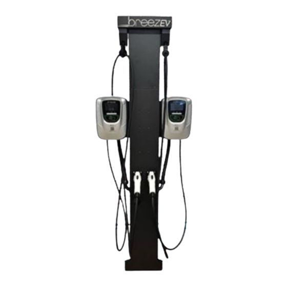
- Page 1 breezEV Level 2 Charging Station Install Guide BreezEV offers best-in-class hardware and technical support. If you have any questions during installation, please do not hesitate to contact us. 3 June 2022 Page | 1...
-
Page 2: Table Of Contents
Table of Contents Safety and Compliance ................................3 Before Installation, Please Read Summary of Shipping Boxes ............................4-6 Specifications ..................................7 Dimensions ..................................8-10 Wiring Diagram & Requirements ............................11 Tools Required ................................... 12 Wall-Mount Installation Mechanical Installation ..............................13 Electrical Connections .............................. -
Page 3: Safety And Compliance
Safety and Compliance SAVE THESE SAFETY INSTRUCTIONS This manual contains important instructions that must be followed during installation of a breezEV Charging Station. WARNINGS This manual contains important instructions for breezEV EVC-L2 series that shall be followed during installation, operation, and maintenance of the unit. Read all the instructions before using this product. -
Page 4: Summary Of Shipping Boxes
Summary of Shipping Boxes CHARGER Part Name Label/Part # on Box Box Contents Example Drawing/Image of Box Contents Charger Head EVC-L2-48A-L1-1-XXXX Charger head (either screen or non-screen unit) (QTY 1) For Example (4G Cellular, AmpUp 5YR LITE Plan) Charger User Manual (QTY 1) EVC-L2-48A-L1-1-4G-D-AU-L- Wall-Mount Bracket (QTY 1) 4G-5... - Page 5 NON-CABLE MANAGEMENT PEDESTAL (EVC-L2-ACC-BB) Part Name Label/Part # on Box Box Contents Example Drawing/Image of Box Contents Pedestal Lower EVC-L2-ACC-LPK Lower pedestal main section (QTY 1) Section Lower pedestal cover (QTY 1) UL Listed Junction Box w/ integral terminal block (QTY 1) Bag of hardware (QTY 1) Pedestal Base Plate (QTY 1) Existing concrete mounting bolts/washers...
- Page 6 SIDE BY SIDE PEDESTAL MOUNTING BRACKET Part Name Label/Part # on Box Box Contents Example Drawing/Image of Box Contents Bracket for EVC-L2-ACC-SSB Side by side bracket (QTY 1) either pedestal Bag of hardware (QTY 1) style to allow for side by side install of chargers WALL-MOUNT CABLE MANAGEMENT PEDESTAL BRACKET...
-
Page 7: Specifications
SPECIFICATIONS 3 June 2022 Page | 7... -
Page 8: Dimensions
DIMENSIONS CHARGER 3 June 2022 Page | 8... - Page 9 NON-CABLE MANGAGEMENT PEDESTAL 3 June 2022 Page | 9...
- Page 10 CABLE MANGAGEMENT PEDESTAL 3 June 2022 Page | 10...
-
Page 11: Wiring Diagram & Requirements
WIRING DIAGRAM & REQUIREMENTS Key Requirements 1. EV charging stations shall be on a dedicated electrical circuit. 2. Each station shall be protected with a 2-pole common trip circuit breaker (non-GFCI type) as indicated by the below table: 3. If a pedestal with 2 chargers is installed with a single feed, the circuit breaker must be rated at 2X the options listed in the table above. -
Page 12: Tools Required
TOOLS REQUIRED The following tools are required: 1. Wire strippers 2. Phillips screwdriver/Torq screwdrivers/Allen head screwdrivers 3. Adjustable pliers and/or wrenches 4. Multimeter 5. Tape measurer and level 6. Pencil 7. Drill 3 June 2022 Page | 12... -
Page 13: Wall-Mount Installation
WALL-MOUNT INSTALLATION Mechanical Installation 3 June 2022 Page | 13... -
Page 14: Electrical Connections
Electrical Connections GROUNDING INSTRUCTIONS This product must be grounded. If it should malfunction or break down, grounding provides a path of least resistance for electric current to reduce the risk of electric shock. This product is equipped with a cord having an equipment grounding conductor and a grounding plug. - Page 15 3. Install the liquid tight cable gland fitting for the incoming power wires and liquid tight. Make sure to properly tighten down the fitting with pliers so that the gasket is compressed and there is no risk of water entering. 4.
- Page 16 6. Attach the 3 incoming power wires like shown to the terminal block inside the charger housing using the provided screws. Tighten down to 10lbf/in. Install the wire strain relief clamp to ensure that the wires cannot be pulled out of the charger. 7.
- Page 17 8. Connect the white, green, and black wires to the terminal block as shown with provided screws. Tighten down to 10lbf/in. Plug the blue communication wire into the green communication terminal as shown. Install the wire strain relief clamp to ensure that the wires cannot be pulled out of the charger. 9.
- Page 18 3 June 2022 Page | 18...
-
Page 19: Installation
LOWER PEDESTAL INSTALLATION (either non-cable management or cable management styles) Concrete Pad Requirements NOTE: The requirements below are the manufacturers minimum recommendations only. The location, dimensions, and composition of the concrete pad for supporting the pedestal should always adhere to local building codes. •... - Page 20 Stainless Steel Base Plate Installation Follow the same procedure for both non-cable management and cable-management pedestals. When pouring new concrete, purchase a breezEV Wet Concrete Pedestal Anchor Kit ( EVC-L2-ACC-ANCHOR KIT WET) 1. Using the provided template, set the 4 J-bolts in place (see below for template). 2.
- Page 21 3 June 2022 Page | 21...
-
Page 22: Installation
Installation of Chargers to the Pedestal 1. Remove the front cover of the charger housing following the directions shown on p14. 2. Remove mounting bracket from the back of the charger housing and install to pedestal using provided hardware, or in the case of a side-by-side install, install to the side-by-side mounting bracket. 3. - Page 23 5. Install the incoming power wires as described on p15-17. 6. Install the charging cable set as described on p15-17. 7. Remove the screws holding the charger housing to the wall mount bracket (either attached to the pedestal or to the side-by-side mounting bracket). Properly attach the front charger cover to the back cover following the steps described on p17.
- Page 24 8. Attach the single or dual charger to either side of the pedestal, or as shown below attach the side-by-side mounting plate to the lower pedestal section. 9. Install the straight or right-angle liquid tight fittings to the proper knockouts on the pedestal base. 3 June 2022 Page | 24...
- Page 25 10. Install the UL listed junction box with terminal block inside of the lower pedestal (skip this step if it is factory installed). Pull the incoming power wires into the UL listed box and properly terminate them to the terminal block.
- Page 26 CABLE MANGEMENT PEDESTAL INSTALLATION Follow all installation steps above to properly mount the base plate, mount the lower pedestal section and complete all electrical wiring. Once the above steps are complete, continue to add the Upper Cable Management Pedestal section: 1.
- Page 27 3. Attach charging cables to cable tensioners using the cable clamps. Note that there are different sized inserts provided for the cable clamps designed for either the 40A or 48A cable sets. Ensure that the proper insert is being utilized. Recommendation: the cable should not touch the ground when properly hung from the cable tensioner.
-
Page 28: Activating Station On Ampup
ACTIVATING STATION ON AMPUP Apply the correct AmpUp QR code detail with matching serial #s to the face of the charger. 3 June 2022 Page | 28... -
Page 29: Status Descriptions On Charger
STATUS DESCRIPTIONS ON CHARGER Normal: 3 June 2022 Page | 29... -
Page 30: Abnormal/Troubleshooting
STATUS DESCRIPTIONS ON CHARGER Abnormal/Troubleshooting Errors and warning messages: 3 June 2022 Page | 30...
Need help?
Do you have a question about the breezEV EVC-L2-D Series and is the answer not in the manual?
Questions and answers