Advertisement
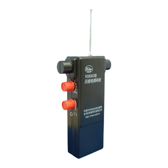
R3500D DIRECTION FINDING RECEIVER KIT
Thanks for your purchase from us. This model is the upgrade of PJ-80 – an 80-m ARDF direct
conversion receiver kit. It keeps the characteristics of simple, low cost, easy to build, and suitable
for the fox hunting and electronic homebrewing activities among youngsters, especially for the
students of elementary and middle schools.
Cautions
The power supply is switched by the earphone plug. After use, please unplug the earphone
•
to switch off the power supply.
Monophonic earphone is not compatible with this receiver. Use the stereo earphone
•
instead as attached.
Pay close attention to differ the 3 diodes: VD1 (1N60), VD2 (FV1043) and VD3 (3V6). They
•
look very similar, but the letters printed on the body of diode can easily tell.
The English manual is for your reference only. Please refer to the attached Chinese manual
The English manual is for your reference only. Please refer to the attached Chinese manual
The English manual is for your reference only. Please refer to the attached Chinese manual
•
for more information.
Note there is an error in the circuit diagram. The center lead of the Ferrite (Magnetic) Rod
•
Antenna is connected to GND as shown on the Compoment Placement Drawing
and the PCB legend.
Rev. A3 – 13 June 2022 - Updates by Jan Verduyn SDR-Kits Ltd
SDR-Kits www.SDR-Kits.net
SDR-Kits is CRKITS Authorised Distributor for Europe
ASSEMBLY MANUAL FOR
Rev. A3
Updated 13 June 2022
Written by CRKITS
http://www.crkits.com
Page 1 of 6
Advertisement
Table of Contents

Summary of Contents for SDR-Kits R3500D
- Page 1 Note there is an error in the circuit diagram. The center lead of the Ferrite (Magnetic) Rod • Antenna is connected to GND as shown on the Compoment Placement Drawing and the PCB legend. Rev. A3 – 13 June 2022 - Updates by Jan Verduyn SDR-Kits Ltd Page 1 of 6...
- Page 2 A. Main Specifications 1. Frequency coverage: no narrower than 3.5 - 3.6 MHz 2. Sensitivity: No less than 600 meters (when receives T3500B fox transmitter with vertical antenna) 3. Directivity: The minimum distance for exhibiting directivity is less than 3 meter 4.
- Page 3 D. Alignment 1. DC check point (1) Voltage across the zener diode VD3: 3.4 - 4.4 volt (2) The bias of transistor V1: The voltage across R4 shall be 0.4 - 1 volt (potentiometer RP1 set to maximum gain position, the Ic of V1 will be 0.4 - 1 mA) The bias of transistor V2: The voltage across R10 shall be 1.5 - 3 volt (the Ic of V2 will be 1.5 - 3 mA) The bias of V3: The voltage across R15 shall be 2 - 2.5 volt (Ic of V3 will be 2 - 2.5 mA) Normally you don't have to adjust the bias, because the design can cover the variance of the...
- Page 4 R15, and test again. The minimum distance on which a cario-pattern can be maintained is 3 meters. * R3500D has a charger socket for charging rechargeable batteries. You don't have to take out the batteries for charging. However, there is no charging or protection circuit built-in, so please make sure the charger can match the voltage, polarity and type of the rechargeable batteries.
- Page 5 Part List for R3500D ARDF Receiver Kit (1) Item Value Identification and comments 18k, 5~20k BRN-GRY-ORG-GLD BRN-GRN-ORG-GLD ORG-WHT-ORG-GLD BRN-BLK-RED-GLD 6.8k BLU-GRY-RED-GLD BRN-BLK-RED-GLD BRN-BLK-RED-GLD 3.9k ORG-WHT-RED-GLD 100k BRN-BLK-YEL-GLD BRN-BLK-RED-GLD 150 ohm BRN-GRN-BRN-GLD 4.7k YEL-VIO-RED-GLD 910 ohm or 820 ohm, 300~1.5k WHT-BRN-BRN-GLD or GRY-RED-BRN-GLD...
- Page 6 SDR-Kits www.SDR-Kits.net SDR-Kits is CRKITS Authorised Distributor for Europe Part List for R3500D ARDF Receiver Kit (2) 470μ electrolytic capacitor 0.1μ 0.1μ 0.01μ 1N60 Glass body diode FV1043 Glass body diode 3.5-4.4V Zener Glass body diode 9014 Transistor, TO-92 9014...
Need help?
Do you have a question about the R3500D and is the answer not in the manual?
Questions and answers