Table of Contents
Advertisement
Quick Links
Advertisement
Table of Contents

Summary of Contents for electrogas MB
- Page 1 Servomotors for butterfly valves VF, VFH elektrogas.com EE157 -1209...
-
Page 2: Table Of Contents
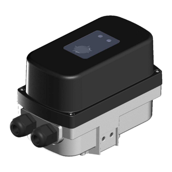
Standards and approvals ………………………….. x Description Servomotors MB/MZ are designed to operate VF and VFH butterfly valves, used in three-stage control (MB) or with electronic positioning control (MZ), of gas and air flow in combustion processes. Features DC motor with multi-stage spur gearbox. -
Page 3: Application
VF..MZ excess of air or gas, VF butterfly valve can be used, coupled to a Lambda sensor for ratio correction. VF..MB Fig. 2 - In case of combustion process with pre-heated air, VFH butterfly valve can be used MZ servomotor. -
Page 4: Technical Specifications
ELEKTROGAS – MANUALE TECNICO Technical specification Tab. 1 Actuator type MB basic adjusting position operated by cams MZ advanced adjusting position by analogue signals Overall dimensions See fig. 4 Weight 2 Kg Rotation angle 0 / 90° Precision of positioning ±0.25°... -
Page 5: Operation Mb
ELEKTROGAS – MANUALE TECNICO Operation This unit is designed for all applications that require high precision control of rotary movement between 0° and 90° . Inside the compact servo drive housing there is a DC electric motor, a gearbox and a control unit with a 16-bit microcontroller. Fig.5 Main terminal board Warning LED2 (red) -
Page 6: Manual Mode
ELEKTROGAS – MANUALE TECNICO LED1 Opening (B2) Automatic/ Manual (S1) Closing (B1) Fig.6 Manual mode For a simplified commissioning, the actuator can be operated manually. The manual mode is useful to determine the operating positions for the process, such as the High/Low fire positions. To enter in the manual mode press the switch S1 downwards (LED1 lights up). -
Page 7: Automatic Mode
ELEKTROGAS – MANUALE TECNICO Automatic mode In the automatic mode the angular position corresponds to the input analogue signal provided by a setpoint device. Factory setting allows full range of operation (0-90° ) but, as above described, MIN and MAX position can be set within this range in manual mode. An output analogue signal proportional to angular position is also provided. -
Page 8: Dip Chart
ELEKTROGAS – MANUALE TECNICO DIP chart Input analogue signal 0-10V 9 10 9 10 0-20mA 9 10 4-20mA Output analogue signal 9 10 0-10V 9 10 4-20mA (0-20mA) programmable by means of T1 Behaviour without input signal (4-20mA) Open position 9 10 9 10 Closed position... -
Page 9: Operating States
ELEKTROGAS – MANUALE TECNICO Operating state Normal operation Tab.x Status LED3 Warning LED2 State description GREEN Fast flashing Automatic mode Slow flashing Manual mode Slow flashing Lighted up when Setting of the MIN and MAX positions position has been (Manual mode) memorized Slow flashing Permanent light... -
Page 10: Standards And Approvals
ELEKTROGAS – MANUALE TECNICO Product identification Tab.2 Model Type B= basis Z= advanced Running time 15 s 30 s 60 s 7...60 s continuous Voltage A= 230VAC 50/60Hz B= 110VAC 50/60Hz C= 24VAC/DC Inputs 0-10 V 0-20 mA 4-20 mA Outputs...
Need help?
Do you have a question about the MB and is the answer not in the manual?
Questions and answers