Table of Contents
Advertisement
Quick Links
Advertisement
Table of Contents

Related Manuals for Vitec Multimedia FIM-102D

Summary of Contents for Vitec Multimedia FIM-102D
- Page 1 FIM-102D MATRIX FIBER INTERFACE INSTRUCTION MANUAL...
- Page 2 FIM-102D Matrix Fiber Interface Instruction Manual © 2004 Vitec Group Communications All Rights Reserved Part Number 810319 Vitec Group Commmunications, Inc. 4065 Hollis Street Emeryville, CA 94608-3505 U.S.A. A Vitec Group Company Clear-Com is a registered trademark of Vitec Group Communications.
-
Page 3: Table Of Contents
Description .................................1-1 Connecting Intercom Stations To The Central Matrix ..................1-1 Connecting Interface Modules To The Central Matrix..................1-5 Using The FIM-102D In Conjunction With The EF-1M As A Stand-Alone Party Line Extender..1-6 FIM-102D Two Fiber Configuration........................1-6 FIM-102D Front Panel Connectors And Lights....................1-8 FIM-102D Rear Panel Connectors.........................1-10... - Page 4 MAINTENANCE............................3-1 Troubleshooting Tips ...............................3-1 Preventative Maintenance ............................3-3 GLOSSARY............................... 4-1 SPECIFICATIONS ............................. 5-1 CLEAR-COM LIMITED WARRANTY ......................6-1 Factory Service................................6-2 Warranty Repair.................................6-3 Non-Warranty Repair ...............................6-3 FIM-102D FIBER INTERFACE...
-
Page 5: Operation
Matrix using fiber-optic cables at distances of up to 12 miles (20 km). The system consists of one FIM-102D at the Matrix-frame end and another FIM-102D unit at the Matrix-station end. Connecting the pair of interfaces with fiber rather than with the standard 4-wire twisted copper, gives you advantages such as increased security from electromagnetic and RF interference, flexibility in equipment placement, ease of maintenance and often, reduced cost. -
Page 6: Connecting Intercom Stations To The Central Matrix
CONNECTING INTERCOM STATIONS TO THE CENTRAL MATRIX The Clear-Com FIM-102D system transmits audio and data signals from 1 or 2 intercom stations or interfaces to the Matrix frame through the process illustrated in Figure 2. Figure 1: Connecting Intercom Stations to the Central Matrix 1-2 ... - Page 7 FIM-102D FIBER INTERFACE...
- Page 8 4. The first FIM-102D then converts the multiplexed digital signal into an optical signal. 5. The first FIM-102D then transmits the optical signal over up to 12 miles (20 km) of fiber-optical cable to the second FIM-102D unit, where a similar but reverse process occurs to convert the signal back to its original format.
- Page 9 WARNING: Always use extreme caution with fiber-optic equipment. Never look directly into the light port or into the end of the optical fiber while either FIM-102D unit is operating. Even if you do not see visible light, eye damage is possible.
-
Page 10: Connecting Interface Modules To The Central Matrix
CONNECTING INTERFACE MODULES TO THE CENTRAL MATRIX With a pair of FIM-102D units you can also remotely connect Clear-Com rack-mounted Matrix interface modules to the central Matrix. For example, using a Clear-Com CCI-22 dual party-line interface at one end, you can connect two independent, external 2-wire party line systems to the central Matrix from a distance of up to 12 miles (20 km). -
Page 11: Using The Fim-102D In Conjunction With The Ef-1M As A Stand-Alone Party Line Extender
USING THE FIM-102D IN CONJUNCTION WITH THE EF-1M AS A STAND-ALONE PARTY LINE EXTENDER Using a Clear-Com EF-1M at each end of a FIM-102D set, you can extend Clear-Com or RTS 2-wire party line intercoms over a fiber-optic link independent of a Matrix intercom system. - Page 12 FIM-102 One-Fiber Configurations These configurations may be offered at a later date. 1-8 FIM-102D FIBER INTERFACE...
-
Page 13: Fim-102D Front Panel Connectors And Lights
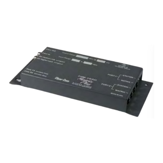
FIM-102D FRONT PANEL CONNECTORS AND LIGHTS Figure 4: Front Panel of FIM-102D Unit FIM-102D FIBER INTERFACE... - Page 14 Fiber Out Fiber Optic ST type receptacle for connection of transmit Fiber Optic Cable to other FIM-102D unit. Fiber In Fiber Optic ST type receptacle for connection of receive Fiber Optic Cable from other FIM-102D unit. RX Optical Link On (green) indicates presence of sufficient optical signal from other FIM-102D unit for communication.
-
Page 15: Fim-102D Rear Panel Connectors
FIM-102D REAR PANEL CONNECTORS Figure 5: Rear Panel of FIM-102D Unit FIM-102D FIBER INTERFACE 1-11... - Page 16 For Station end of FIM-102D link. Connect RJ-45 cord from here to Station or Interface. Future Buss connector This connector is only used when FIM-102D is mounted in an optional multiple unit equipment shelf. The shelf supplies power to the FIM-102D via this connector.
- Page 17 Figure 6: FIM-102D Shown With Wall Mounted Power Supply FIM-102D FIBER INTERFACE 1-13...
-
Page 18: Installation
INSTALLATION UNPACKING When you receive your Clear-Com FIM-102D System, check to make sure you have received all components of the system. The following items make up a Clear-Com FIM-102D: • FIM-102D multiplexer/demultiplexer unit • External power supply You will require two FIM-102D sets to complete a circuit. -
Page 19: Installing And Fim-102D Unit In A Rack
SELECTING AND INSTALLING FIBER-OPTIC CABLE The person installing the FIM-102D units is responsible for providing the fiber optic cable runs. The FIM-102D will operate with either Single-Mode or Multi-Mode Fiber Optic Cable. You will experience the best distance performance when using Single-Mode cable as shown in Table 1. -
Page 20: Maximum Fiber Lengths
WARNING: Do not use the FIM-102 optical output to identify cables. Never look directly into the end of the optical fiber while either end of the system is operating. Even if you do not see visible light, eye damage is possible. FIM-102D FIBER INTERFACE... - Page 21 Inspect the fiber ends and clean them with clean, dry compressed air or with Kim-Wipes that have been saturated with isopropyl alcohol. Fingerprints or other dirt on the optical connector end surfaces will reduce the received optical signal level. 2-4 FIM-102D FIBER INTERFACE...
-
Page 22: Connecting Fiber Optic Cable To The Fim-102
FIBER CONNECTORS Figure 1: ST Optical Connections on an FIM-102D Unit's Front Panel Refer to Figure 1 before connecting the optical fiber to the ST optical connectors on the FIM-102D unit’s front panel. The FIM-102D is compatible with industry standard ST-type connectors. You may use installed backbone cables or dedicated cables with it. - Page 23 • transmitter ST “Fiber Out” at the near end connects to receiver ST “Fiber In” at the far end and • transmitter ST “Fiber Out” at the far end connects to receiver ST “Fiber In” at the near end. Figure 2 illustrates the entire wiring scheme for the FIM-102D system. 2-6 ...
-
Page 24: Connecting Audio/Data Cables To The Fim-102D
Figure 2: Wiring an FIM-102D to intercom stations or interfaces RJ-45 connectors on the FIM-102D unit’s rear panel connect the unit to audio and data inputs and outputs as shown in Figure 2. Figure 3 illustrates the CAT-5 and above cable pinout configuration. The maximum length for CAT-5 cables is 10,000 feet (3 km). -
Page 25: Cat-5 Cable Pinout Diagram
8 7 65 4 32 1 8 7 6 5 4 3 21 Pair 1 Audio output Pair 2 RS-422 data input Pair 3 Audio input Pair 4 RS-422 data output Figure 3: CAT-5 Cable Pinout Diagram 2-8 FIM-102D FIBER INTERFACE... -
Page 26: Maintenance
MAINTENANCE TROUBLESHOOTING TIPS Listed on the next page are some of the more common problems that you may experience, their possible causes and suggested solutions. FIM-102D FIBER INTERFACE... - Page 27 If you are unable to resolve a problem with your FIM-102 unit, call Clear-Com Intercom Systems at (510) 496-6666 and ask for the Service Department. See the Warranty Chapter for more information. 3-2 FIM-102D FIBER INTERFACE...
-
Page 28: Preventative Maintenance
PREVENTIVE MAINTENANCE Every two years verify the adequacy of optical power at the far end of each optical fiber with an optical power meter. FIM-102D FIBER INTERFACE... -
Page 29: Glossary
2-wire party line, telephone, etc. The interface is connected to a central matrix port. The external non-4-wire device is then connected to the interface. mode A term used to describe a light path through a fiber as in multimode or single mode. FIM-102D FIBER INTERFACE... - Page 30 The glass core of a single-mode fiber is smaller in diameter than the core of a multimode fiber, so that the light signal transmitted over the core is more concentrated than with multimode fiber, which allows the signal to travel further. Single-mode fiber evolved from multimode fiber as production methods improved. 4-2 FIM-102D FIBER INTERFACE...
- Page 31 (WDM) A method of multiplexing optical signals developed for use on fiber-optic cable. Each signal is assigned a particular wavelength on the light spectrum and therefore many signals can be transmitted simultaneously without interfering with each other. FIM-102D FIBER INTERFACE...
-
Page 32: Specifications
Digital, TDM, 24-bit, 48k samples/sec Input Impedance 600 Ohms balanced Output Impedance 30 Ohms balanced Maximum Input Level (600 Ohms) +17 dBm (peak) Maximum Output Level (from 30 Ohms balanced) +17 dBm into 600 Ohms Frequency Response (@8 dBm) FIM-102D FIBER INTERFACE... - Page 33 Power Connector 2.5mm Circular Input Voltage Range 9-18 Vdc Power Consumption (@13.8V per end, all channels at full level) <5 watts ° ° Temperature Range –40 to 65 Humidity Range 0 to 95% non-condensing A/C Adapters supplied 5-2 FIM-102D FIBER INTERFACE...
- Page 34 RS-422, Balanced TTL Levels, 0 to 150 kBits/sec Jitter 1.12 msec* *Higher rates possible dependent upon user system jitter tolerance. Power Requirements Voltage 9-18 VDC Caution: Absolute maximum voltage is 18 VDC. Equipment damage may occur at higher voltages. FIM-102D FIBER INTERFACE...
- Page 35 While Clear-Com makes every attempt to maintain the accuracy of the information contained in its product manuals, that information is subject to change without notice. Performance specifications included in this manual are design-center specifications and are included for customer guidance and to facilitate system installation. Actual operating performance may vary. 5-4 FIM-102D FIBER INTERFACE...
- Page 36 VGC, and shipping damage. Products with their serial numbers removed or defaced are not covered by this warranty. This warranty is the sole and exclusive express warranty given with respect to Clear-Com products. It is the responsibility of the user to determine before purchase that this product is suitable for the user's intended purpose. FIM-102D FIBER INTERFACE...
-
Page 37: Factory Service
By talking with our representatives, many problems can be resolved over the phone. You can also send a fax to our customer service department or send an email to support@clearcom.com. 6-2 FIM-102D FIBER INTERFACE... -
Page 38: Warranty Repair
Equipment that is not under warranty must be sent prepaid to Vitec Group Communications, Inc. If requested, an estimate of repair costs will be issued prior to service. Once repair is approved and repair of equipment is completed, the equipment will be shipped freight collect from the factory. FIM-102D FIBER INTERFACE... - Page 39 6-4 FIM-102D FIBER INTERFACE...
Need help?
Do you have a question about the FIM-102D and is the answer not in the manual?
Questions and answers