Advertisement
Quick Links
EPF Series USER MANUAL
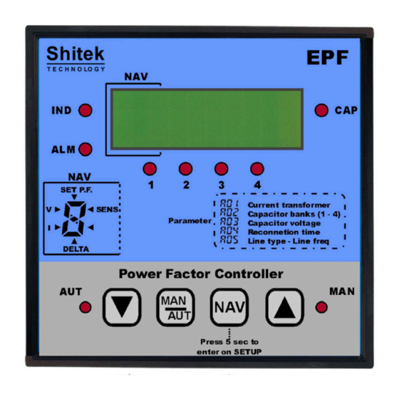
Power Factor Controller
The power factor controller was designed with signal processing
technology to ensure accurate control of all the electrical systems
of the plant such as: VOLTAGE, CURRENT, COSφ, THDI% and
through a sofisticate algorithm, optimal use of capacitors bank
and contactors, taking into account the distortion phenomena of
industrial plants.
Using digital signal filtering techniques, it is able to separate
only the components from the other harmonic components
basic sinusoidal voltage and current, on which the phase shift is
measured.
The device consecutively displays all the measurements on the 4
digit 7 segment display in order to ensure easy reading of the data
in any environmental condition.
The user can access the adjustment using four user keys of the
instrument, manually insertion banks, displaying measurements
and alarms.
INSTALLATION
The power factor controller must be installed on a three-phase or
single-phase line with a 50-60 Hz mains frequency and quadrature
insertion. EPF need to be connected to a CT to measure the line
current (L1) and to the AC voltage (L2-L3) to measure the voltage
of the network.
The power supply inputs and the other connections of the device
must be protected by fuses suitably sized according to the regulations
in force and to the expected power consumption.
The control outputs must be suitably connected to the respective
intervention devices.
Shitek Technology S.r.l.
Via Malerbe, 3 - 36040
Grumolo delle Abbadesse (VI) - ITALY
Tel. +39 0444 18 00 191
Fax +39 049 79 60 910
Email/web: info@shitek.it - www.shitek.it
SET UP
EPF allows the setup of the parameters of the POWER FACTOR
and SENSITIVITY by pressing the NAV button until the LED
corresponding to the parameter to be changed lights up.
NOTE: The sensitivity is the time interval that the EPF regulator have
to wait between 2 consecutive insertions.
To access the SETUP menu it is necessary to set the device to
manual operation, switch off all the outputs and press the NAV
button for 3sec until the display shows PAR.
To select the parameter to modify press shortly the NAV button and
to change the value, press the buttons UP▲ o DOWN▼.
The regolations to be made in this menu are:
A01 -> Current transformer ratio
A02 -> Power of each capacitor bank
A03 -> Capacitors nominal voltage
A04 -> RC time minimum time to wait between the disconnection of
a capacitor bank and a subsequent reconnection.
A05 -> Select three-phase or single-phase and 2 or 4 quadrant.
A06 -> Line Frequency (50-60Hz)
A07 -> High THDI% threshold
A08 -> Over THDI% threshold
A09 -> Over Temp threshold
NORMAL OPERATIONS
When the SETUP operations have been completed, the display
shows the value of the Power Factor currently calculated in the
plant, the voltage of line, current measured on the TA (true RMS) and
the Δ kVAr missing reactive power to reach the Set cosφ setpoint .
Note: if the measured power factor is not stable, reverse the
connections in terminals T1 and T2 of the input amperometric.
Press the NAV button to scroll through the various pages of the main
menu in the sequence:
Power Factor - Voltage - Current - Delta Power - SENS - SET cosφ-
THD I% - TEMP.
NAV
SET P.F.
v >
I >
DELTA
The segment of the NAV display shows the type of measure displayed.
Switching on the segment therefore indicates respectively whether
the display on the right corresponds to: Voltage, Current, Delta Power,
Sensitivity, THD I%, Set Power Factor, Temperature (the temperature
value is showed with the DOT led on).
MAN_000008_eng_EPF_ed7_07_2020
>
THD I
>
SENS
>
TEMP
Advertisement

Summary of Contents for SHITEK EPF Series
- Page 1 Tel. +39 0444 18 00 191 Fax +39 049 79 60 910 Email/web: info@shitek.it - www.shitek.it MAN_000008_eng_EPF_ed7_07_2020 EPF Series USER MANUAL SET UP Power Factor Controller EPF allows the setup of the parameters of the POWER FACTOR and SENSITIVITY by pressing the NAV button until the LED corresponding to the parameter to be changed lights up.
- Page 2 For example, in the case of an HIGH VOLTAGE alarm, the LED ALM and the segment V of the NAV display will blink and For a continuous development of its products, Shitek technology the voltage measure is displayed. The system to be protected...
Need help?
Do you have a question about the EPF Series and is the answer not in the manual?
Questions and answers