Table of Contents
Advertisement
Quick Links
Advertisement
Table of Contents

Related Manuals for SMAR MB-700


Summary of Contents for SMAR MB-700
- Page 1 M B 7 0 0 M E...
- Page 2 Specifications and information are subject to change without notice. Up-to-date address information is available on our website. web: www.smar.com/contactus.asp...
- Page 3 Introduction INTRODUCTION The MB-700 is a powerful multifunction module from LC700 family that can be used isolated or integrated to the SYSTEM302. The module can perform multi function in MODBUS protocol like gateway MODBUS TCP/IP and MODBUS RTU, MODBUS data concentrator and Peer-to-Peer communication between MODBUS slave devices.
- Page 4 MB-700 – User’s Manual...
-
Page 5: Table Of Contents
Using the Fault Indication............................2.4 Installing the System302 ..........................2.4 Getting the License for DFI OLE Server...................... 2.5 Connecting the MB-700 to the Subnet ......................2.5 Chapter 3 - CONFIGURATION ......................3.1 Updating the Firmware ..........................3.1 Setting the MB-700 through Software ......................3.6 Creating a New Plant ..............................3.7... - Page 6 Redundancy ..............................6.4 MB-700 as a Concentrator and Supervision via DFI OPC Server............. 6.5 MB-700 working as a Concentrator and Supervision via DFI OPC Server and “Peer-to-peer” .... 6.6 MB-700 as Concentrator, Supervision via DFI OPC Server, “Peer-to-peer” and network redundancy6.7 Multiple MODBUS RTU Masters Accessing a LC700 through only one Port (P2) ........
- Page 7 Appendix B - CABLING........................B.1 Ethernet Cable Specification........................B.1 Serial Cable Specification ........................... B.1 EIA-232 Interface ............................... B.1 Connecting the MB-700 to the LC700 ........................B.4 EIA-485 Interface ............................... B.6 Dimensions ..............................B.7 Appendix C – SPECIFICATIONS FOR MB-700................C.1 Technical Specifications ..........................
- Page 8 MB-700 – User’s Manual VIII...
-
Page 9: Glossary
A bridge isolates two networks. It has the function of only passing the data addressed to it to the other side. It works in the data link layer. Bypass: When the MODBUS message is received by the MB-700 it is passed to the other network where it is connected. CCCF: Block that configures the communication between the MB-700 and slave devices. - Page 10 MB-700 – User’s Manual Function Blocks: Device language programming of industrial automation. To each function block it is associated an algorithm and configuration parameters associated. The change of information between blocks will be done through links between inputs and outputs of the function blocks.
- Page 11 “Peer-to-peer” Communication: Communication way allowing changes of information between devices in the same hierarchic level. In applications using MB-700, peer-to-peer means change of information between devices. Router: Router is responsible for sending the data packages through an external network until they reach their destination.
- Page 12 MB-700 – User’s Manual Transmission media: It is the physical media, where the port is sent. Transmitter: Device that includes both the electronic board and the transducer/sensor that sends the field variable read from this device.
-
Page 13: References
References REFERENCES Function Blocks Instruction Manual Syscon Manual LC700: User’s Guide LC700: LC700 Configuration Manual XIII... - Page 14 MB-700 – User’s Manual...
-
Page 15: Chapter 1 - Overview
Power Supply PS-AC-R. Cable Standard Ethernet DF54 – Twisted-Pair (100 Base T) Cable – length 2 m. Software DFI OLE Server (Used during configuration and when the MB-700 is set as a data concentrator) System302 DHCP Server (optional) Windows NT workstation (Service Pack 3 or higher) -
Page 16: Main Characteristics
The MB-700 has a modular concept and may be put in panels inside a control room or in sealed boxes in the field. It is indicated to remote applications avoiding that user needs to walk to the place where the process is located to configure the MODBUS device. -
Page 17: System Integration
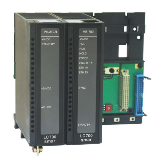
Supports up to 31 slaves connected to the EIA-485 bus. Power Supply – PS-AC-R This module is the power supply for the MB-700 and LC700 system. It supplies 5V necessary to the IMB. This module has functions of diagnose and dedicated LEDs that indicate normal operation in failure conditions what makes possible troubles to be easily detected, especially in systems with several units. - Page 18 MB-700 – User’s Manual...
-
Page 19: Chapter 2 - Installation
Chapter 2 INSTALLATION ATTENTION: If any of the steps are not followed, it may cause a malfunctioning of the system. Fixing Racks and Modules Note the Figures 2.1 and 2.2 and proceeds according instructions. Module LEDs Introduction to connect-tag RS-232 and Ethernet Interfaces Terminals Screw for fixation of... -
Page 20: Installing The Module In The Rack
MB-700 – User’s Manual B. Jumper W1 – when connected, it allows that rack to be powered by the previous rack C. Module support – piece of the superior part of the rack D. DIN Rail - Base to fix the rack. It must be fixed tightly in the place of the rack mounting E. -
Page 21: Installing The Rack In The Din Rail
1.25A manual manual Figure 2.3 – MB-700 Hardware Basic System To wire the MB-700 and HUB uses a standard twisted-pair cable. The MB-700s have simple RJ-45 connectors. No special tools or skills are required. Installation is simple and very fast. -
Page 22: Using The Fault Indication
3. Plug the Ethernet cable (standard pair cable) connecting MB-700 to the HUB/Switch 4. The MB-700 will automatically get an IP address from the DHCP server, but if this server is not available, it will initially have a fixed IP address (this fixed IP may be changed through the FBTools- see topic “Connecting the MB-700 to the Subnet”) -
Page 23: Getting The License For Dfi Ole Server
To connect more than one MB-700, the following steps must be completely executed to each MB- 1. Plug the Ethernet cable DF54 of the MB-700 module to the Switch (or HUB) of the subnet where the MB-700 will be put. - Page 24 Default Gateway. ATTENTION Do not use the address 192.168.164.100 once it is the default address used by the MB-700. 10. Click the OK button. 11. Run the FBToolsWizard.exe (located in the working directory of Smar) directly from the shortcut...
- Page 25 13. Click the Connect button to see the available modules. Figure 2.8 – Dfi Download – Connect (1) 14. Select the target MB-700 module in the option Module using as reference the serial number (refer to the external identification label of the MB-700).
- Page 26 MB-700 – User’s Manual Figure 2.9 – Dfi Download – Choose Module 15. To go ahead it is necessary to stop the firmware that is running in the MB-700 Processor. Click the HOLD button. 16. After executing the previous step, the module will not running the firmware so it will stop all its activity.
- Page 27 Figura 2.11 – Dfi Download – Connect (2) 18. Click the Connect button to return network. Select the target MB-700 module in the option Module using as reference the serial number (refer to the external identification label of the MB- 700).
- Page 28 Figure 2.13 – IP Address - Specify ATTENTION Do not use the IP 192.168.164.100 once it is the default address used by the MB-700. Be certain this address is not being used. Take note of the IP address attributed and relate them to the serial numbers of each module. This will help during identification and diagnose of the possible failures.
- Page 29 27. End of connection procedure of the MB-700 in the subnet. NOTE If it is necessary to set more than one MB-700, run the following command to clear the ARP table, before setting the next MB-700. C:\>arp –d 192.168.164.100 <enter>...
- Page 30 MB-700 – User’s Manual 2.12...
-
Page 31: Chapter 3 - Configuration
CONFIGURATION Updating the Firmware Plug the Ethernet cable DF54 of the MB-700 module to the Switch (or HUB) of the subnet where the MB-700 will be put. OBS: For point to point connections (the MB-700 connected directly to the PC) use the cross cable DF55. - Page 32 Default Gateway. ATTENTION Do not use the address 192.168.164.100 once it is the default address used by the MB-700. 10. Click the OK button. 11. Run the FBToolsWizard.exe (located in the working directory of Smar) directly from the shortcut “FBTools Wizard”, or directly using the shortcut “FBTools Wizard”.
- Page 33 If the user does not follow this step this might imply in serious consequences. Figure 3.4 – Dfi Download – Choose Device 15. To go ahead it is necessary to stop the firmware that is running in the MB-700 Processor. Click the HOLD button.
- Page 34 MB-700 – User’s Manual Figure 3.5 – Dfi Download – Entry Confirmation Screen in Hold Mode 17. Be sure the HOLD LED is ON. After stopping the firmware execution in the module, the window will appear again (See Figure 3.6).
- Page 35 21. During the download, it shows the progress indication bar. See Figure 3.9. Figure 3.9 – Dfi Download – Progress Screen 22. When the download ends, it shows a status message. At this moment, the MB-700 will be on Run mode. Click the OK button. (Be sure the RUN LED is lit).
-
Page 36: Setting The Mb-700 Through Software
Setting the MB-700 through Software ATTENTION To have the MB-700 properly set by SYSCON it must be assured the procedure “Connecting the MB-700 to the Subnet” was done properly. The MB-700 is totally set through Function Blocks available in the Fieldbus Foundation standard. -
Page 37: Creating A New Plant
Once it is connected to the Ethernet bus or to a Workstation, the MB-700 is detected and next it is attributed a fixed IP address or variable depending on the process set via FBTools, eliminating any troubles with the dip switches or address duplication. - Page 38 MB-700 – User’s Manual Figure 3.15 – Screen to Configure the Server (1) – Syscon 6. Select the name Smar.DFIOLEServer0 in the parameter Server ID and click the OK Button. 3.16 – Screen to Configure the Server (2) – Syscon Add the Fieldbus channel In the MB-700 device, add the CCCF (Configuration) and Resource Blocks.
-
Page 39: Chapter 4 - Mb-700 Function Blocks
Figure 4.1 – MB-700 Configuration Example as Serial Master - Serial to TCP/IP: Selecting this option the MB-700 will work as a serial slave device (EIA-232 or EIA485) and as TCP/IP master. One MODBUS RTU command that reaches the MB-700 via serial (EIA-232/EIA485) will be sent in the TCP/IP port. -
Page 40: Modbus Addresses
For this scenario, MB-700 does not support CCSM and CCCM Blocks. MODBUS Addresses User must attribute a Modbus address to the MB-700. However this address must be unique in the Modbus networks where the MB-700 is connected through Ethernet or serial ports. In this case, user must set the DEVICE_ADDRESS parameter. -
Page 41: Configuring The Tcp Media
This delay time is used when the device (master or slave) has slowness in the serial processing. If MB-700 acts as Serial Master, the delay will be between a slave answer and the next MB-700 request. Figure 4.3 – Time Delay between Rx and Tx (MB-700 as Serial Master) If MB-700 acts as Slave Serial, the delay will be between the Master request and MB-700 answer for the Master. -
Page 42: Parameters
None ALERT_KEY Unsigned8 1 to 255 None MODE_BLK DS-69 See Mode Parameter BLOCK_ERR Bitstring(2) D / RO It specifies the preferable MB-700 to REDUNDANCY_ROLE Unsigned8 Not used Main Active, when there redundancy. It shows which MB-700 is Active REDUNDANCY_STATE Unsigned8... - Page 43 IP Slave 12. Waiting time, in milliseconds, millise TIME_DELAY Unsigned 16 between the reception (Rx) and the next transmission (Tx) of MB-700. Time used for the Ethernet port to TCP_SCAN_TIME Float D/RO scan the Modbus variables. Table 4.1 - Legend: Store / Mode Column – Store: data storage (D – Dynamic; S – Static; N – Non volatile) / Mode: minimal necessary mode for user modify the parameter (OOS –...
-
Page 44: Block Ccsm - Concentrate Supervision Master
2- Not using Config View If user sets the mode “1” will make the MB-700 to get the data from the slave devices in a much faster and optimized way. This will increase the updating of parameters of these blocks that are mapped in the Modbus slave devices. -
Page 45: B - Data Supervision
MB-700 Function Blocks ADDRESSING 1 - SLAVE_ADRR Parameter: In this parameter user will inform address of the slave device in the Modbus RTU network. 2 - B_ADDRESSi Parameter: Boolean data. User must type the Modbus addresses of the discrete variables that are required to monitor. -
Page 46: C - Supervision Status
16 float variables that can be mapped for supervision of the Modbus slave device. C - Supervision Status 1 - SCAN_STATUS Parameter: Status parameter of the scan done by the MB-700 in the communication with serial slave devices. Message Description... - Page 47 MB-700 Function Blocks Data Type Valid Range/ Default Store/ Parameter Unit Description (Length) Options Value Mode P_EU_ADDRESS_A Information to locate percentage variable DS-265 as well scaling conversion. … … … … … … … … P_EU_ADDRESS_A Information to locate percentage variable DS-265 as well scaling conversion.
-
Page 48: Block Cccm- Concentrate Control Master
For example, a slave must be connected in the serial port of the MB-700 and another might be connected in the Ethernet network or even in another serial port of another MB-700. User needs only to inform the Modbus address of each device, addresses of Modbus variables and a MB-700 internal “link”... - Page 49 MB-700 Function Blocks Figure 4.6 - Functioning of a Communication “Peer-to-peer” in a MODBUS Device A Peer-to-Peer example is showed in the Figure 4.6. Assume that wish read a variable from slave 1 and write in the slave 2. Each variable (of slave1 read and of slave2 write) have a Modbus address, which must be obtained of the slave device (consult the manufacturer’s manual).
-
Page 50: B - Addressing
The format for the data among the available types can be selected in this parameter. Refer to the Appendix C for details about data types. PORT_NUMBER User must inform the MB-700 port to be used for communication between slaves: Ethernet, P1 or SLAVE_ADDRESS In this parameter, it must inform the Modbus address of the slave device. -
Page 51: C - Monitoring Data
User must inform the following parameters: PORT_NUMBER User must inform the MB-700 port to be used for communication between slaves: Ethernet, P1 or SLAVE_ADDRESS In this parameter, it must inform the Modbus address of the slave device. -
Page 52: D - Supervision Status
MB-700 – User’s Manual D - Supervision Status 1 - Parameter COMM_STATUS This parameter indicates if the communication between slaves was established properly. If the corresponding bit is in logic level 1, it means there was an error during writing/reading of the respective parameter. - Page 53 MB-700 Function Blocks Valid Data Type Default Store / Parameters Range/ Unit Description (Length) Value Mode Options Information to generate constants A and B em EU_ADDRESS _IN3 DS-266 S / OOS equation Y=A*X+B plus the addresses in a slave device.
-
Page 54: Block Ccdl - Concentrate Data Logger
It is an optimized mechanism to bring data stored from the LC700. • To start the FIFO Data Logger block of the LC700 when the communication with a MB-700 master (for example a HMI) fails, the CCDL block sends a Modbus command to the variable in the LC700 pointed by STOP_SCAN_ADDRESS. -
Page 55: Parameters
LOGGER_ADDRESS Unsigned16 beginning NUM_REGISTER Unsigned16 D / RO Number of logged FIFO registers MB-700 may force the trigger of data STOP_SCAN_ADDRESS Unsigned16 0 - 9999 logger writing TRUE to a Modbus variable in the slave Modbus device. Block next... - Page 56 MB-700 – User’s Manual 4.18...
-
Page 57: Chapter 5 - Adding Modbus To The
“TCP to Serial”. Bypass (TCP/IP to serial): The MB-700 passes the MODBUS message transmitting it to a lower level of the network. The MB-700 acts as TCP/IP Modbus to serial Modbus RTU (485 ou 232) converter. -
Page 58: Off Line Configuration
A - Configuring the IP of the MB-700 Set the IP of the MB-700 connecting it to the subnet, for more details about how to configure the IP address, refer to the chapter 2 “ Connecting the MB-700 to the Subnet”. - Page 59 Figure 5.3 - Adding Block CCCF Block Steps to configure the CCCF Block: • In the SYSCON find the MB-700. • Right click <VB_VFD> icon. A new window will appear. Select the New Block option. • A window will appear. Select the CCCF Block, give a name to it and click the OK button to...
- Page 60 MB-700 – User’s Manual Figure 5.4 – Configuration Screen CCCF Block The following parameters must be adjusted: BAUD_RATE: Adjust to 57600. BYPASS_DIRECTION: TCP to Serial. NUMBER_RETRANSMISSIONS: Choose "3". TIMEOUT: "1000" (1000 ms). MODE_BLK: Select "Auto". DEVICE_ADDRESS: Make sure that in the MODBUS network there is not any other address with the number shown for this parameter.
- Page 61 Adding Modbus to the MB-700 Figure 5.5 – MB-700 Blocks Configuration Example 2) MB-700 working as Concentrator For the MB-700 works as Concentrator, it is necessary to configure, besides the previous blocks, the CCSM Block. CCSM Block Steps to configure the CCSM Block:...
- Page 62 MB-700 – User’s Manual Input/Output Data Type Modbus Adresses LED 1 Digital 00001 LED 2 Digital 00002 LED 3 Digital 00003 LED 4 Digital 00004 LED 5 Digital 00005 LED 6 Digital 00006 LED 7 Digital 00007 LED 8 Digital...
- Page 63 Adding Modbus to the MB-700 The user should set the transmitter inputs. In the window above search for the parameters P_EU_ADDRESS_A1 to P_EU_ADDRESS_A28. Click the P_EU_ADDRESS_A1 parameter. User will set the following parameters: FROM_EU_100% Inform the maximum value to the input variable read in the transmitter 1.
- Page 64 Figure 5.8 - Block Configuration Finished 3) MB-700 working as Peer-to-peer For the MB-700 works as Peer-to-peer between Modbus devices in the same serial network, it is necessary to configure, besides the Resource and CCCF Blocks, the CCCM Block. CCCM Block To configure the CCCM block, follow the steps below.
- Page 65 For example, considering the example of Figure 5.1 where Modbus slaves devices are in MB-700 serial port and is desirable transfer a variable of a slave 1 to slave 2. Then, the reading variables in OUT_xx parameters and the write variables in IN_xx parameter of the CCCM block are associates.
- Page 66 MB-700 – User’s Manual Figure 5.11 - Setting the CCCM Block To configure the reading variables, find the parameter EU_ADDRESS_IN1. Inform the required parameters. They are similar to the parameters EU_ADDRESS_OUT1 of the CCSM block. However SLAVE_ADDRESS must be equal to the value of the address of the second slave of the MOBDUS network.
- Page 67 Select Export tags. A window will open like below asking where the file with the tags will be saved. • Click the Save button. Figure 5.13 - Choosing the Folder for Export Tags Start the communication with the MB-700 by clicking in the On Line button. 5.11...
-
Page 68: On Line Configuration
Block to “Apply”. This will update the configuration of the CCSM Block. On Line Configuration It is possible to set blocks of the MB-700 on line with the device connected to the network and functioning. It is only necessary that user right-clicks the block and select On Line Characterization. -
Page 69: Configuration
Adding Modbus to the MB-700 Figure 5.14 – Example of MB-700 Architecture working as Serial Bypass for TCP Configuration The RESOURCE Block must have its parameter MODE_BLK put in “auto”. The procedures to configure the CCCF Block are similar to the previous application, except by the BYPASS_DIRECTION parameter now selected to “Serial to TCP”. - Page 70 MB-700 – User’s Manual Figure 5.15 - Setting the BYPASS_DIRECTION Parameter in the CCCF Block The configuration of the Modbus Slaves in the CCCF Block follows the steps below: • If the configuration has only one a Modbus slave for a determined IP address, the parameter SLAVE_ADDRESSES must be used.
-
Page 71: Mb-700 Working As Peer-To-Peer
On Line. 2 - MB-700 working as Peer-to-peer For the MB-700 works as Peer-to-peer in the TCP/IP, the user must follow the defined steps for the Off Line Configuration in the item MB-700 working as Serial Peer-to-peer, and, besides this, the... -
Page 72: Mb-700 As A Tcp/Ip Modbus Slave
The Modbus address of the parameter to be monitored is fixed for each CCSM Block and depends on the block instantiation (it is indicated in the STRATEGY parameter). To provide the redundancy, the MB-700 Blocks must answer like Slave Modbus as Active and also as Standby. - Page 73 Using the Data Logger Description The MB-700 may store data Logs from a LC700 Data Logger Block (FIFO). So, during normal reading of the Concentrate Data Logger it checks if there are data stored in the correspondent slave. In case there are data stored it will read these data and clear the log buffer of the slave.
- Page 74 MB-700 – User’s Manual In case the data type is REAL, using the same 1000 registers and knowing that one REAL value requires 2 registers for each sample so the calculation becomes: 500/280 = 2 CCDL blocks. The CCDL Block works together with the supervision blocks. Thus there must be supervision blocks pointing to the same address of the slave so that the CCDL Block works properly.
- Page 75 CCDL blocks in cascade, it is only necessary to repeat the same configuration to all the data logger blocks. In this way, the MB-700 will start to use blocks according to the order of instantiation indicating which is the next block stored through the parameter NEXT_BLOCK_LOG.
- Page 76 MB-700 – User’s Manual 5.20...
-
Page 77: Chapter 6 - Scenarios
Serial ports EIA-232 and EIA- 485 allow 3 LC700 to be connected to the MB-700. Two of the controllers are connected through the EIA-485 bus and a third one is connected through a radio link. This last one is a remote unit because its physical location is far from the MB-700 master. -
Page 78: Multiple Masters Tcp/Ip Communicating Directly With Several Lc700S And "Peer-To-Peer" Between Lc700S Within A Same Modbus Rtu Network
Multiple Masters TCP/IP Communicating Directly with several LC700s and “Peer-to-peer” between LC700s within a same Modbus RTU Network Figure 6.2 – MB-700 Application Example as MODBUS Gateway and Link of Point to Point Equipments (Serial Master) In this application, the MB-700 supports the following simultaneous functionality:... -
Page 79: Multiple Masters Tcp/Ip Communicating Directly With Several Lc700S And "Peer-To-Peer" Between Lc700'S Of Different Modbus Rtu Networks
Multiple Masters TCP/IP Communicating Directly with several LC700s and “Peer-to-peer” between LC700’s of different Modbus RTU Networks Figure 6.3 – MB-700 Application Example Link Point to Point Equipments Local and Remote (through TCP) and Modbus Gateway In this application, the MB-700 supports the following simultaneous functionality: CONF700 downloads/uploads via TCP/IP including remotely. -
Page 80: Multiple Masters Tcp/Ip Communicating Directly With Lc700S, "Peer-To-Peer" And Network Redundancy
MB-700 connects TCP/IP masters to the MODBUS slaves through Ethernet ETH1 and its serial channel EIA-485. The second MB-700 connects TCP/IP masters through the redundant Ethernet ETH2 and the serial EIA-232 channel where it is connected a radio link between MB-700 and the slave CPUs. -
Page 81: Mb-700 As A Concentrator And Supervision Via Dfi Opc Server
CCSM Block. Through the DFI OPC Server these variables are read from an OPC client. In this way when user monitors one variable, the access is faster, because the MB-700 stores this value in its memory in the parameter sheet of the CCSM Block. -
Page 82: Working As A Concentrator And Supervision Via Dfi Opc Server And "Peer-To-Peer
MB-700 working as a Concentrator and Supervision via DFI OPC Server and “Peer-to-peer” Figure 6.6 – MB-700 Application Example as Serial Data Concentrator and Link of Modbus Slaves In this application, the MB-700 supports the following simultaneous functionality: CONF700 downloads/uploads via TCP/IP including remotely. -
Page 83: As Concentrator, Supervision Via Dfi Opc Server, "Peer-To-Peer" And Network Redundancy6.7
MB-700 as Concentrator, Supervision via DFI OPC Server, “Peer-to-peer” and Network Redundancy Figure 6.7 – MB-700 Application Example as Concentrator and Peer-to-peer with Redundancy of CPU In this application, the MB-700 supports the following simultaneous functionality: CONF700 downloads/uploads via TCP/IP including remotely. -
Page 84: Multiple Modbus Rtu Masters Accessing A Lc700 Through Only One Port (P2)
MB-700 through the serial EIA-485 channel. Each of these MB-700s connects to one point of the Ethernet. In this Ethernet it is connected a MB-700 whose EIA-485 channel forms a bus of MODBUS RTU network. In this network, connect the LC700. In the port P2... -
Page 85: Chapter 7 - Redundancy Hot Standby
MB-700; • Redundancy of the MB-700 Module: How the MB-700 module is responsible for all store and control of the information interchange between Modbus slaves, the redundancy of this module assures the availability of the supervision and control system functioning without interruption;... -
Page 86: Mb-700 Module Redundancy
In the SYSCON configuration, the tag for the transducer block can be any, preferentially a meaningful tag concerned to the MB-700 tag or to the plant. Be careful to not use tags already in use in the same plant. -
Page 87: Configuring The Network Redundancy
5 - Install two HUBs or switches. Each NIC must be connected to one of them in such a way that two LAN are assembled isolated from each other. 6 - That way, each one of the MB-700 modules can be connected to one of the HUBs obeying the subnet ranges predefined (e.g. First MB-700, IP=192.168.164.51 / Subnet Mask 255.255.255.0 and Second MB-700, IP=192.168.163.51 / Subnet Mask 255.255.255.0). -
Page 88: Configuring Hot Standby Redundancy
The last updated good data will be chosen by the DFI OLE Server to be forwarded to the client. When the MB-700 is in Hot Standby mode, the DFI OLE Server will preferably choose the data that came from the Active module, to be forwarded to the client. - Page 89 Redundancy Hot Standby setting Sync_Main. After that, through the synchronism path the other one automatically will be set as Backup. This designates physically who should be, in other words, the Preferential and the Redundant processor module respectively. This way, Main and Backup can be understood simply as labels.
-
Page 90: First Time Configuration Procedure
MB-700 – User’s Manual SYNC STATUS DESCRIPTION The modules are in perfect synchronism. The Active continuously updates Synchronized the Standby databases. If a spare module is connected in the panel with the same Role of that one is Warning: Role already running, this warning is shown. -
Page 91: Changing Configuration
6 - If necessary, perform Assign Tag for all the field devices. Wait until the Live Lists of all the channels are complete. So, configure the system through the Active module executing all necessary downloads exactly the same way for a non-redundant MB-700 system. 7 – As soon as downloads are completed successfully, the transducer will show the following phases: •... -
Page 92: Adding Redundancy To An Existing System
Stand Alone status. SYNC_CABLE Physical Connection The physical connection is simple as shows the picture below: Figure 7.4 – Physical Connection of the MB-700 Redundancy Channel Additional Parameter Table IDShell Transducer - New Parameters and Values for MB-700 Redundancy... - Page 93 Redundancy Hot Standby DataType Default Parameter Valid Range/ Options Units Store/Mode Description (length) Value 1:Passive 2:Active 3:Backup Redundancy Role for the local 4:Active_Not_Link_Master RED_ROLE_L Unsigned8 D / RO device 7:Sync_Idle Idem FUNCTION_IDS description. 8:Sync_Main 9:Sync_Backup Redundancy State for the local 0:Not Ready device RED_STATE_L...
- Page 94 MB-700 – User’s Manual Description of meaning of RED_BAD_CONDITIONS_L / R Bits Variable Modbus H1-1 (not used) H1-2 (not used) H1-3 (not used) LiveList Res_1 Res_2 Res_3 Table 7.2 – Description of Bits 7.10...
-
Page 95: Appendix A - Troubleshooting
Appendix A TROUBLESHOOTING The MB-700 allows a few initialization procedures to solve specific problems. These resources are: ATTENTION Any form of initialization will cause a serious impact in the system! Reset Click the right Push-Button (see details in the following figure which shows the two small buttons located above of the Modbus 232 connector) and the system will execute the RESET taking some seconds for correct system initialization. -
Page 96: When To Use The Factory Init/Reset Procedure
Follow these steps: 2.1- Assure the MB-700 is turned ON and that it was connected to the Subnet. In case it was not, use the procedure “Connecting the MB-700 to the Subnet”. Be sure that the HOLD LED is ON. - Page 97 Troubleshooting 9. The MB-700 was working properly, I turned it off again and now any kind of reset does not work and the HOLD LED keeps constantly ON and/or blinking. In this case it is necessary to use the Boot flash.
- Page 98 MB-700 – User’s Manual...
-
Page 99: Appendix B - Cabling
EIA-232 Interface Connecting MB-700 to SI-700 To connect the serial EIA-232 port of the MB-700 to the SI-700 module (RS232/RS485 converter) it is necessary a DF59 cable or it must be assembled a cable according to the specifications next. DF59 – Cable used to connect MB-700 to SI-700... - Page 100 Figure B.2 – Connecting MB-700 to SI-700 or DF58 Connecting the MB-700 to DF51/FC302 To connect the RS232 serial port of MB-700 to the serial port of the DF51, FC302 or other MB-700, it should be made a cable with the RJ12 connectors, following the next picture.
- Page 101 Cabling CABLE CONNECTION DIAGRAM DB9 (FEMALE) RJ12 CABLE ASSEMBLING PIN 1 PIN 1 TERMINAL 1 FRONT Figure B.4 – Connecting the MB-700 to the Computer...
-
Page 102: Connecting The Mb-700 To The Lc700
MB-700 – User’s Manual Connecting the MB-700 to the LC700 There are two cables to connect the MB-700 to the LC700. The assembly schematics are showed below. Cable EIA-232 to connect CPU-700-X3* and MB-700 Part number C232-3-700 – cable to connect CPU-700 and MB-700... - Page 103 THERMINAL 1 LABEL ID ADHESIVE PROTECTION FIAT CABLE 26 AWG 4 VIAS SHIELDED CABLE 26 AWG 2 PAIRS THERMINAL 1 PIN 1 FRONT (* means D or E) Figure B.6 – Connecting the MB-700 to the LC-700 (LC700 with Redundancy)
-
Page 104: Eia-485 Interface
GND: Reference for communication signal EIA RS-485 Table B.1 – Pins of Terminal Block Description The example below shows the connection between MB-700 to the 485 network. For long distances from the 485 cable, it recommends to use terminators (resistors 120ohms) in both network ends. -
Page 105: Dimensions
Cabling Dimensions Figure B.8 - Dimensions... - Page 106 MB-700 – User’s Manual...
-
Page 107: Technical Specifications
Appendix C SPECIFICATIONS FOR MB-700 Technical Specifications CONTROLLER Type 32 Bit RISC (CPU Clock @25 MHz) Performance 50 MIPS Code Memory 2 Mbytes, 32 Bits Flash Memory (Firmware recordable) Data Memory 2 Mbytes, 32 Bits NVRAM (Data storage and configuration) -
Page 108: Data Types Available For The Parameter Datatype
ETHERNET or CCCF 04 DISCRETE POINTS BOTH CCCM1 CCCM16 (Support up to 16 Blocks CM) Observation: The MB-700 supports Mixed function like Bypass and Concentrator and Peer- To-Peer. Data Types Available for the Parameter DATATYPE Number of Data Data Type Description... -
Page 109: Scale Conversion
Technical Specifications • Data allocation for Swapped Unsigned32 data type (little-endian) Modbus Data Address 40001 1234 40002 5678 Scale Conversion The Blocks that support Scale conversion are listed below: • CCSM EU_ADDRESS_A/EU_ADDRESS_B • CCCM EU_ADDRESS_IN1 a EU_ADDRESS_IN2 EU_ADDRESS_OUT1 a EU_ADDRESS_OUT2 •... -
Page 110: Data Structure For Mb-700
MB-700 – User’s Manual Data Structure for MB-700 Block Structure – DS-64 This data structure consists of the attributes of a block. Element Name Data Type Size Block Tag VisibleString DD MemberId Unsigned32 DD ItemId Unsigned32 DD Revision Unsigned16 Profile... -
Page 111: Alarm Discrete Structure - Ds-72
Technical Specifications Alarm Discrete Structure – DS-72 This data structure consists of data that describes discrete alarms. Element Name Data Type Size Unacknowledged Unsigned8 Alarm State Unsigned8 Time Stamp Time Value Subcode Unsigned16 Value Unsigned8 Event Update Structure – DS-73 This data structure consists of data that describes a static revision alarm Element Name Data Type... -
Page 112: Address Structure - Ds-264
MB-700 – User’s Manual Address Structure - DS-264 Element Name Data Type Size Modbus Address of Value Unsigned16 Number of Bytes Unsigned8 Address Structure - DS-265 Element Name Data Type Size From EU 100% Float From EU 0% Float To EU 100%... -
Page 113: Appendix D - Srf - Service Request Form
Appendix D smar SRF – Service Request Form Proposal Nº: MB-700 COMPANY INFORMATION Company: _____________________________________________________________________________________________________ Unit/Department:___________ _____________________________________________________________________________________ Invoice:______________ ________________________________________________________________________________________ COMMERCIAL CONTACT Full Name:______ _______________________________________________________________________________________________ Phone:___ _________ _________________________ _________ _________________________ Fax: _______________________ Email: _______________________________________________________________________________________________________ TECHNICAL CONTACT Full Name: _____________________________________________________________________________________________________ Phone: _________ _________________________... - Page 114 MB-700 – User’s Manual...
-
Page 115: Appendix E - Smar Warranty Certificate
Appendix E SMAR WARRANTY CERTIFICATE SMAR guarantees its products for a period of 24 (twenty four) months, starting on the day of issuance of the invoice. The guarantee is valid regardless of the day that the product was installed. SMAR products are guaranteed against any defect originating from manufacturing, mounting,... - Page 116 13. It is the customer’s responsibility to clean and decontaminate products and accessories prior to shipping them for repair, and SMAR and its dealer reserve themselves the right to refuse the service in cases not compliant to those conditions. It is the customer’s responsibility to tell SMAR and its dealer when the product was utilized in applications that contaminate the equipment with harmful products during its handling and repair.
Need help?
Do you have a question about the MB-700 and is the answer not in the manual?
Questions and answers