Table of Contents
Advertisement
Quick Links
Advertisement
Table of Contents

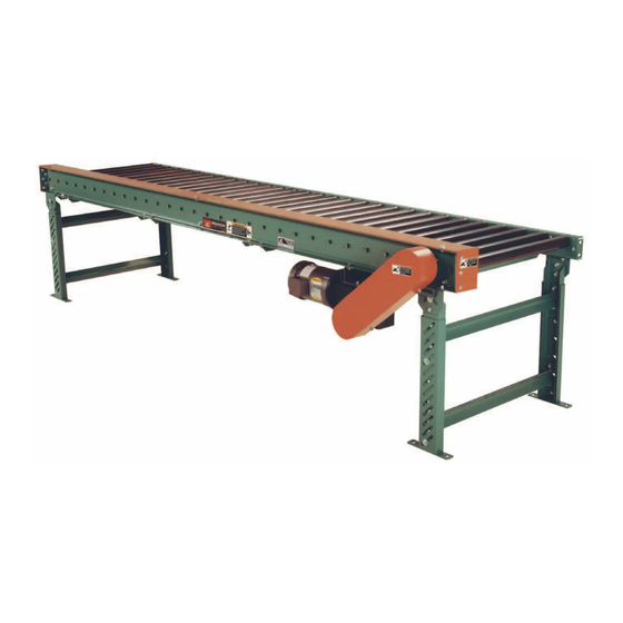
Summary of Contents for Roach Conveyors 192CDLR
-
Page 2: Table Of Contents
TROUBLE SHOOTING AND REPLACEMENT PARTS ........13 TECH HANDBOOK FOR CDLR ..............2 -Trouble Shooting / Serial Plate ..............13 -Warning Labels ..................2 CAUTIONS, WARNINGS AND HAZARDS ...........3 MODEL 192CDLR -Introduction ....................3 -Parts List ....................14 -Cautions, Warnings and Hazards ...............3 -Underneath and Sidemount Drive Drawings ..........14 SAFETY INFORMATION ................4... -
Page 3: Cautions, Warnings And Hazards
CAUTIONS, WARNINGS AND HAZARDS INTRODUCTION This manual was prepared as a “how- unit in an application receiving little or it is your responsibility to become familiar to-guide” for installers, end-users and no maintenance. You may find that a with the unit, to know potential hazards maintenance personnel. -
Page 4: Safety Information
SAFETY INFORMATION IMPORTANT SAFETY GUIDELINES WARNING: All personnel coming in contact with this conveyor should be aware of the following safety guidelines BEFORE USING OR WORKING AROUND CONVEYOR. NOTE: ALWAYS notify Roach Manufacturing whenever any conveyor is ® used in an application or condition other than was originally intended. Failure to notify Roach may allow conveyor to be ®... -
Page 5: Receiving And Inspection
RECEIVING AND INSPECTION SHORTAGES, DAMAGES AND RETURN AUTHORIZATIONS NOTE: Do not return goods to factory without prior, written return authorization. Unauthorized returns are subject to refusal at factory. Before uncrating, check the quantity of accompanying freight documentation) For damaged shipments, consult fac- items received against bill of lading to be checked to ensure receipt of ALL units tory to determine if entire shipment must... -
Page 6: General Installation Information
GENERAL INSTALLATION INFORMATION ATTACHING BED SECTIONS NOTE: It is critical for bed sections to be field assembled in proper sequence following bed section labels.. When preparing to install conveyor, first bed section labels. Refer to bed sec- mating beds in accordance with bed locate all component sections in the actual tion drawing for location of supports and section labels (and bed section drawing). -
Page 7: Start-Up Procedures
START-UP PROCEDURES DRIVE CHAIN AND SPROCKET ALIGNMENT To check drive sprocket alignment, it is imperative that conveyor is shut “OFF” and power source is locked out before any adjustments are attempted. Set up and maintenance of drive sprocket To check drive sprocket alignment, it is sprockets as required. -
Page 8: Gear Reducer Vent Plug
START-UP PROCEDURES ® GEAR REDUCER WITH POSIVENT PosiVent Unique design incorporates a single seam construction. Factory filled with synthetic lubrication for universal mounting. Lubed for life, no oil changes are required. To expedite the installation and start-up process, all gear red ucers are shipped filled with oil. The reducers are sealed and lubed for life and require no oil changes. -
Page 9: Maintenance Safety Precautions
MAINTENANCE SAFETY PRECAUTIONS BEFORE PERFORMING MAINTENANCE Only trained personnel shall perform maintenance functions. Before maintenance operations are performed, conveyor must be shut “OFF” and disconnects locked in the “OFF” position to prevent unit from unauthorized start-up. One of the most important guidelines for maximizing conveyor Do not perform any work on conveyors or conveyor system operation and personnel safety is to implement a regular mainte- while in operation unless it is impossible to otherwise conduct... -
Page 10: Maintenance And Lubrication
MAINTENANCE AND LUBRICATION PERIODIC MAINTENANCE SCHEDULE MODEL NO.__________ WEEKLY RECOMMENDED MAINTENANCE SCHEDULE* COMPONENT DETAIL OF MAINTENANCE Pillow Block/Flange Bearings Lubricate in dirty, dusty or moist/wet conditions Confirm placement of all guards, pop out rollers, warn- Unit Safety Check ing labels & check for loose bolts, nip points & other hazards. -
Page 11: Recommended Lubricants
MAINTENANCE AND LUBRICATION RECOMMENDED LUBRICANTS MISC. LUBRICANTS LUBRICANT BRAND/DESCRIPTION General Purpose Grease Shell Dolium R (Shell Oil Co.) (For -30°F to 300°F operation)* (or suitable equivalent) For Extreme Temperature Operation Mobiltemp SHC-32 (Mobil Oil Corp.) (-90°F to 350°F operation)* (or suitable equivalent) Washdown Application* Shell Alvania No. -
Page 12: Report On Miscellaneous Maintenance Performed
MAINTENANCE AND LUBRICATION REPORT ON MISCELLANEOUS MAINTENANCE PERFORMED REPORT ON MAINTENANCE CONVEYOR REPAIRED INSPECTION DETAIL OF MAINTENANCE COMPLETED (OR INSPECTION) MARK NO. DATE LIST PARTS REPLACED OR REPAIRS... -
Page 13: Trouble Shooting And Replacement Parts
TROUBLE SHOOTING AND REPLACEMENT PARTS TROUBLE SHOOTING / SERIAL PLATE TROUBLE SHOOTING TROUBLE PROBABLE CAUSE REMEDY A. Drag on conveyor A. Inspect entire conveyor for obstruction causing drag B. Frozen sprocket on chain. B. Check and inspect all sprockets and bearings. Motor &... -
Page 14: Model 192Cdlr
Replacement Parts on page 13). Recommended Spare Parts are shown in red. Charted are item no. and part description When ordering use example below. Example: Need a replacement tread roller for a 192CDLR. Part No: SN 123456 - 6 - Tread Roller Assembly... -
Page 15: Model 251Cdlr
MODEL 251CDLR PARTS LIST FOR UNDERNEATH AND SIDE MOUNT DRIVE ITEM# DESCRIPTION End Bed Section Assembly Bolt-in Butt Coupling (4”) Chain Guard End Cover Bolt-in Butt Coupling (6”) Channel Cross member TREAD ROLLER ASSEMBLY BOTTOM CHAIN GUARD TOP CHAIN GUARD 6”... -
Page 16: Model 251Cdlr/297Cdlr Structural
MODEL 251CDLR/297CDLR (STRUCTURAL) PARTS LIST FOR UNDERNEATH AND SIDE MOUNT DRIVE ITEM# DESCRIPTION End Bed Section Assembly Chain Guard End Cover Channel Cross member Tread Roller Assembly Bed Spacer Roller Assembly Bottom Chain Guard Top Chain Guard 6” Side Channel Weld Assembly 4”... -
Page 17: Model 3530Cdlr
MODEL 3530CDLR (STRUCTURAL) PARTS LIST FOR UNDERNEATH AND SIDE MOUNT DRIVE ITEM# DESCRIPTION End Bed Section Chain Guard End Cover 8” Side Channel Weld Assembly 6” Side Channel Weld Assembly Channel Cross member Tread Roller Assembly Bed Spacer Roller Assembly Bottom Chain Guard Top Chain Guard Chain Loops (Specify Roller Center) -
Page 18: Notes
NOTES... -
Page 19: Warranty
Ma t e r i a l F l o w & C o n v e y o r S y s t e ms 2 1 1 5 0 B u t t e v i l l e R d N E ( P O B o x 5 5 0 ) D o n a l d , O R .
Need help?
Do you have a question about the 192CDLR and is the answer not in the manual?
Questions and answers