
Related Manuals for Gas Detection GTD-2000Tx

Summary of Contents for Gas Detection GTD-2000Tx
- Page 1 GTD-2000Tx GTD-2000Tx Instruction Manual Instruction Manual Read in detail for correct use. Read in detail for correct use.
- Page 2 GTD-2000Tx GTD-2000Tx Instruction Manual Instruction Manual Gas & Flame Gas & Flame Detection System Detection System In case of a problem after purchasing the product, In case of a problem after purchasing the product, please contact the address below. please contact the address below.
- Page 3 Greetings Greetings www.gastron.com www.gastron.com 02_03 02_03 We sincerely thank you for purchasing the product of Gastron Co. Ltd. We sincerely thank you for purchasing the product of Gastron Co. Ltd. Our Gastron Co.Ltd. is a company specialized in Gas detector and Gas Monitoring System, being recognized Our Gastron Co.Ltd.
- Page 4 GTD-2000Tx GTD-2000Tx Contents Conte Instruction Manual Instruction Manual 1. Overview 1. Overview ······································································································································································ ··································································································································································· 2. Structure 2. Structure ······································································································································································· ···································································································································································· 3. Specification 3. Specification ································································································································································ ····························································································································································· 3.1. Basic Specifications ············································································································································ 3.1. Basic Specifications ········································································································································· 3.2. Mechanical Specifications 3.2. ································································································································· Mechanical Specifications ······························································································································...
-
Page 5: Table Of Contents
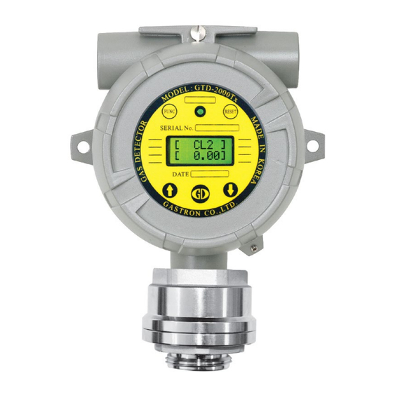
Contents www.gastron.com Contents www.gastron.com 04_05 04_05 7.2.1. Zero Calibration ······································································································································· 7.2.1. Zero Calibration ······································································································································· 7.2.2. Span Calibration ······································································································································ 7.2.2. Span Calibration ······································································································································ ALARM Mode ···················································································································································· 7.3. ALARM Mode ···················································································································································· oubleshooting 8. Troubleshooting ·························································································································································· ·························································································································································· Fault List ····························································································································································· 8.1. Fault List ·····························································································································································... - Page 6 2. Structure Body of GTD-2000Tx is made of Aluminum alloy and the gas sensor module is made of stainless steel. It consists of a Body of GTD-2000Tx is made of Aluminum alloy and the gas sensor module is made of stainless steel. It consists of a complete explosion-proof enclosure (Ex d IIC T6).
- Page 7 3. Speci cations 3. Speci cations www.gastron.com www.gastron.com 06_07 06_07 3.1. Basic Specifications 3.1. Basic Specifications ITEMS ITEMS SPECIFICATION SPECIFICATION Measuring Type Measuring Type Diffusion Diffusion Measuring Value Display Measuring Value Display LCD or OLED Display LCD or OLED Display - Electro-Chemical Cell - Electro-Chemical Cell Measuring Method...
- Page 8 GTD-2000Tx GTD-2000Tx 3. Speci cations 3. Speci ca Instruction Manual Instruction Manual 3.3. Electrical Specifications (Standard Type) 3.3. Electrical Specifications (Standard Type) ITEMS ITEMS SPECIFICATION SPECIFICATION Input Voltage(Standard) Input Voltage(Standard) Absolute min: Absolute min: Nominal: Nominal: requirements IEC1010-1 and CE...
- Page 9 4. Name and Description of Each Part www.gastron.com www.gastron.com 08_09 08_09 mponents 4.1. Components [Figure 2. GTD-2000Tx Components] [Figure 2. GTD-2000Tx Components] ITEMS ITEMS SPECIFICATION SPECIFICATION Housing Body Protects PCB Board built in Sensor and Housing from external environmental change and shock.
- Page 10 - Use a conductor that is 4 mm or longer when coupling ground line. - Use a conductor that is 4 mm or longer when coupling ground line. [Table 1. GTD-2000Tx Description of Configuration] [Table 1. GTD-2000Tx Description of Configuration]...
- Page 11 5. Installation 5. Installation www.gastron.com www.gastron.com 10_11 10_11 It is prohibited for an individual, other than an approved user or a technician responsible for installation and repair from It is prohibited for an individual, other than an approved user or a technician responsible for installation and repair from the head office, to install a gas leak detector on site or open the cover of the installed gas leak detector and manipulate the head office, to install a gas leak detector on site or open the cover of the installed gas leak detector and manipulate it.
- Page 12 GTD-2000Tx GTD-2000Tx 5. Installation 5. Installa Instruction Manual Instruction Manual 5.2. Main PCB Configuration 5.2. Main PCB Configuration [Figure 5. Main PCB Terminal Layout] [Figure 5. Main PCB Terminal Layout] NAME NAME DESCRIPTION DESCRIPTION Power & Output Signal Terminal Power & Output Signal Terminal...
- Page 13 5. Installation www.gastron.com 5. Installation www.gastron.com 12_13 12_13 minal Configuration 5.3. Terminal Configuration ng it with hands and pulling towards ceiling detaches it from the Main PCB. Holding it with hands and pulling towards ceiling detaches it from the Main PCB. screws clockwise (cw) so that terminal does not leave the track then insert Main PCB as the same condition fixing screws clockwise (cw) so that terminal does not leave the track then insert Main PCB as the same condition e disassembly.
- Page 14 Instruction Manual Instruction Manual 5.3.1. Wiring for 4~20mA Source Operation Type 5.3.1. Wiring for 4~20mA Source Operation Type GTD-2000Tx. GND terminal is used in common with GTD-2000Tx. GND terminal is used in common with power. power. Then, turn on the J1 jumper.
- Page 15 PLC side to VISO terminal and power (24V DC) (-) at PLC side to VISO terminal and power (24V DC) (-) 5.4. Installation Cable Length 5.4. Installation Cable Length - min operating voltage) - min operating voltage) ·IMAX : Max. Current of GTD-2000Tx ·IMAX : Max. Current of GTD-2000Tx...
- Page 16 GTD-2000Tx GTD-2000Tx 5. Installation 5. Instal Instruction Manual Instruction Manual [Figure 10. Calculation of GTD-2000Tx Installation Cable Length] [Figure 10. Calculation of GTD-2000Tx Installation Cable Length] COPPER RESISTANCE(ohms/m) COPPER RESISTANCE(ohms/m) METERS METERS 3.31 0.00521 3.31 0.00521 3838 3838 2.08 0.00828 2.08...
- Page 17 6. Detector Operation Flow 6. Detector Operation Flow www.gastron.com www.gastron.com 16_17 16_17 l Operation Status (Power On) 6.1. Initial Operation Status (Power On) . Approx. 30 m of stabilization of time is needed from the initial supply of operation power and it starts to on LCD.
- Page 18 System Mode. at each Program Setting Screen, it returns to the parent step. at each Program Setting Screen, it returns to the parent step. [Figure 11. GTD-2000Tx Mode Configuration] [Figure 11. GTD-2000Tx Mode Configuration] ITEM ITEM...
- Page 19 6. Detector Operation Flow 6. Detector Operation Flow www.gastron.com www.gastron.com 18_19 18_19 6.4. Menu Configuration Table 6.4. Menu Configuration Table LEVEL2 LEVEL2 LEVEL1 LEVEL1 DEFAULT DEFAULT NAME NAME PARAMETER PARAMETER GAS TYPE (Gas Type) GAS TYPE (Gas Type) [DEFIN./USER] [DEFIN./USER] DEFIN.
- Page 20 GTD-2000Tx GTD-2000Tx 7. System Mode 7. System Mo Instruction Manual Instruction Manual 7.1. PROGRAM MODE 7.1. PROGRAM MODE PASSWORD PASSWORD [**] [**] - If password is correct, it enters Program mode. - If password is correct, it enters Program mode.
-
Page 21: Zero Calibration
7. System Mode 7. System Mode www.gastron.com www.gastron.com 20_21 20_21 CALIBRATION MODE 7.2. CALIBRATION MODE ondition may change depending on site condition. condition may change depending on site condition. 1. Zero Calibration 7.2.1. Zero Calibration PASSWORD PASSWORD mode. mode. [**] [**] CALIBRA. -
Page 22: Span Calibration
GTD-2000Tx GTD-2000Tx 7. System Mode 7. System Mode Instruction Manual Instruction Manual 7.2.2. Span Calibration 7.2.2. Span Calibration CALIBRA. CALIBRA. MODE MODE CALIBRA. CALIBRA. [SPAN] [SPAN] SPAN CAL SPAN CAL [ NO] [ NO] - Using a calibration tool, inject the standard gas to the sensor at a flow rate of 500 mL/min for 90 sec. -
Page 23: Alarm Mode
7. System Mode 7. System Mode www.gastron.com www.gastron.com 22_23 22_23 7.3. ALARM MODE 7.3. ALARM MODE PASSWORD PASSWORD [**] [**] ALARM ALARM MODE MODE - It is a setting where Alarm Mode Setting is turned on or off. - It is a setting where Alarm Mode Setting is turned on or off. ALM USED ALM USED can be performed. - Page 24 GTD-2000Tx GTD-2000Tx 7. System Mode 7. System Mod Instruction Manual Instruction Manual A2 TYPE A2 TYPE [INC] [INC] when the value is equal or less than set alarm threshold. when the value is equal or less than set alarm threshold.
-
Page 25: Troubleshooting
8. Troubleshooting 8. Troubleshooting www.gastron.com www.gastron.com 24_25 24_25 . Fault List 8.1. Fault List FAULT MESSAGE FAULT MESSAGE DESCRIPTION & CONDITION DESCRIPTION & CONDITION CAUSE CAUSE FAULT2 FAULT2 Sensor output is above ADC max. value. Sensor output is above ADC max. value. Defective sensor module or transmitter board ADC Defective sensor module or transmitter board ADC FAULT3... -
Page 26: Outline Drawing And Dimensions
GTD-2000Tx GTD-2000Tx 9. Drawings and Dimensions 9. Drawings and Dimensions Instruction Manual Instruction Manual 9.1. Standard Type 9.1. Standard Type [Figure 12. GTD-2000Tx Standard Type Drawing] [Figure 12. GTD-2000Tx Standard Type Drawing]... -
Page 27: Upon Coupling Of Warning Light 9.2. Upon Coupling Of Warning Light
9. Drawings and Dimensions 9. Drawings and Dimensions www.gastron.com www.gastron.com 26_27 26_27 9.2. When Connecting Warning Light 9.2. When Connecting Warning Light... -
Page 28: Upon Coupling Of Raincover 9.3
GTD-2000Tx GTD-2000Tx 9. Drawings and Dimensions 9. Drawings and Dimensio Instruction Manual Instruction Manual 9.3. When Connecting Raincover 9.3. When Connecting Raincover [Figure 14. GTD-2000Tx Raincover Connection Drawing] [Figure 14. GTD-2000Tx Raincover Connection Drawing]... -
Page 29: Notes Before Installation
10. Precautions before Installation 10. Precautions before Installation www.gastron.com www.gastron.com 28_29 28_29 1. Selecting a Place for Installation (Occupational Health & Safety Act Data) 10.1. Selecting a Place for Installation (Occupational Health & Safety Act Data) as leak detector alarm shall be installed in the following places. A gas leak detector alarm shall be installed in the following places. - Page 30 GTD-2000Tx GTD-2000Tx 10. Precautions before Installation 10. Precautions before Installation Instruction Manual Instruction Manual During wiring work, use explosion-proof cable gland at cable inlet or tightly seal cable conduit during metal cable wiring During wiring work, use explosion-proof cable gland at cable inlet or tightly seal cable conduit during metal cable wiring construction to prevent spread of flames in case of explosion or movement of gas, etc.
-
Page 31: Revision Record
11. Revision History 11. Revision History www.gastron.com www.gastron.com 30_31 30_31 VERSION VERSION CONTENTS CONTENTS DATE DATE * Manual Initial Revision * Manual Initial Revision 2012. 01. 31 2012. 01. 31 * Corrected Specification (Added Current Consumption), Corrected Address * Corrected Specification (Added Current Consumption), Corrected Address 2013. - Page 32 Tel +82-31-490-0800 Fax +82-31-490-0801 Tel +82-31-490-0800 Fax +82-31-490-0801 Gas Detection (Australia) Pty Ltd Copyright © Gas Detection (Australia) Pty Ltd 2020 Yeongnam business office / Plant : Yeongnam business office / Plant : 55 Gonghangap-gil 85beon-gil, Gangseogu, Busan Metropolitan City...
Need help?
Do you have a question about the GTD-2000Tx and is the answer not in the manual?
Questions and answers