
Summary of Contents for Teal SMA SUNNY MULTIGATE XT
- Page 1 SUNNY MULTIGATE XT Installation Manual TEAL PN 1060147 | Models Multigate XT1 to XT4 | Revision 2.5 Designed and Manufactured by TEAL Electronics...
- Page 2 TEAL Electronics SMA America, LLC Installation Manual - TEAL PN 1060147 rev 2.5...
- Page 3 (with no limitation) any implied warranties of utility, merchantability, or fitness for any particular purpose. All such warranties are expressly disclaimed. Neither SMA America, LLC nor its distributors or dealers nor TEAL Electronics nor its distributors or dealers shall be liable for any indirect, incidental, or consequential damages under any circumstances.
- Page 4 CAUTION indicates a hazardous situation which, if not avoided, could result in minor or moderate injury. NOTICE is used to address practices not related to personal injury. Installation Manual - TEAL PN 1060147 rev 2.5...
- Page 5 —Increase the separation between the equipment and receiver. —Connect the equipment into an outlet on a circuit different from that to which the receiver is connected. —Consult the dealer or an experienced radio/TV technician for help. Installation Manual - TEAL PN 1060147 rev 2.5...
- Page 6 All installations must conform with the laws, regulations, codes and standards applicable in the jurisdiction of installation. Neither SMA nor TEAL assumes responsibility for the compliance or noncompliance with such laws or codes in connection with the installation of the product.
-
Page 7: Table Of Contents
Product Specifications ......39 Installation Manual - TEAL PN 1060147 rev 2.5... -
Page 8: Table Of Figures
......... 38 XT4S Connections Installation Manual - TEAL PN 1060147 rev 2.5... -
Page 9: Information On This Document
SMA Speedwire/Webconnect Speedwire/Webconnect Sunny Boy 240-US* Sunny Boy, inverter, micro inverter* Sunny Multigate-US Sunny Multigate * The terms “Sunny Boy”, “Sunny Boy 240-US”, “micro inverter” and “inverter” are synonymous in this document. Installation Manual - TEAL PN 1060147 rev 2.5... -
Page 10: Safety
Sunny Boy 240-US micro inverter and the utility grid to feed the alternating current converted by the inverters collectively into the utility grid. The Multigate XT is designed for split-phase operation only. The Multigate XT must be operated in conjunction with SMA Sunny Boy 240-US. Installation Manual - TEAL PN 1060147 rev 2.5... -
Page 11: Skills Of Qualified Persons
• Training in the installation and commissioning of electrical devices and plants • Knowledge of the applicable standards and guidelines • Knowledge of and observance of this document and all safety precautions Installation Manual - TEAL PN 1060147 rev 2.5... -
Page 12: Safety Precautions
• The Multigate XT must be installed in compliance with a Type 4 industrial enclosure with pollution degree 3. • Use only conduit fittings, hubs, or connectors that also meet the requirements of a Type 4 industrial enclosure with pollution degree 3. Installation Manual - TEAL PN 1060147 rev 2.5... -
Page 13: Scope Of Delivery
Installation Manual for Sunny Boy 240-US / Multigate-US 1 for XT1 PIC and RID Labels - Quantity varies by model - For logging 2 for XT2 the PIC and RID numbers during installation 3 for XT3 4 for XT4 Installation Manual - TEAL PN 1060147 rev 2.5... -
Page 14: Product Description
RJ-45 Ethernet connection is directly on the Sunny Multigate to connect the SMA Speedwire/Webconnect system. Multigate XT1E Shown with Door Open and Touch Safe Cover in place Figure 3: Multigate XT1E. Installation Manual - TEAL PN 1060147 rev 2.5... -
Page 15: Multigate Xt1E Shown With Touch-Safe Cover Removed
Multigate XT1E shown with touch-safe cover removed. 80 MIL PVC ACRYLIC ALLOY DEAD FRONT COVER FRONT - DOOR OPENED Figure 5: Multigate XT1E shown with touch-safe door open and touch-safe cover in place. Installation Manual - TEAL PN 1060147 rev 2.5... -
Page 16: Multigate Xt2E
TORQUE TO 5.7 LB-IN KITS (x4) RECESSED DIN OUTPUT TB CUSTOMER RAIL FOR COUPLERS CONNECTION POINTS TORQUE TO 5.7 LB-IN INPUT TB CUSTOMER CONNECTION POINTS Figure 7: Multigate XT2E shown with touch-safe cover removed. Installation Manual - TEAL PN 1060147 rev 2.5... -
Page 17: Multigate Xt2S
OUTPUT TERMINAL BLOCKS CUSTOMER GROUND TORQUE TO 5.7 LB-IN CUSTOMER CONNECTION POINT LANDING INPUT TERMINAL BLOCKS TORQUE TO 5.7 LB-IN CUSTOMER CONNECTION POINT Figure 9: Multigate XT2S shown with touch-safe cover removed. Installation Manual - TEAL PN 1060147 rev 2.5... -
Page 18: Multigate Xt3S
TORQUE TO 5.7 LB-IN TORQUE TO 11.5 LB-IN GROUND RECESSED RAIL - TORQUE CUSTOMER CONNECTION POINT CUSTOMER CONNECTION POINT LANDING TO 5.7 LB-IN Figure 11: Multigate XT3S shown with touch-safe cover removed. Installation Manual - TEAL PN 1060147 rev 2.5... -
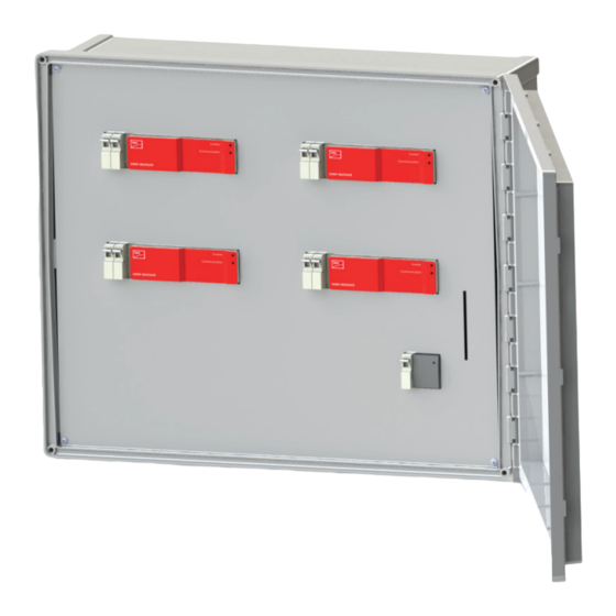
Page 19: Multigate Xt4S
GROUND TORQUE TO 5.7 LB-IN TORQUE TO 11.5 LB-IN RECESSED RAIL - TORQUE CUSTOMER CONNECTION POINT CUSTOMER CONNECTION POINT LANDING TO 5.7 LB-IN Figure 13: Multigate XT4S shown with touch-safe cover removed. Installation Manual - TEAL PN 1060147 rev 2.5... -
Page 20: Type Label And Stickers
Multigate XT and for customer support from the SMA Service Line. The type label must be permanently affixed to the Multigate XT. Figure 14: Example of the Multigate XT Type Label. Installation Manual - TEAL PN 1060147 rev 2.5... -
Page 21: Example Of The Pic/Rid Label Supplied With Each Multigate
TEAL Electronics SMA America, LLC Figure 15: Example of the PIC/RID Label supplied with each Multigate. Installation Manual - TEAL PN 1060147 rev 2.5... -
Page 22: Communication
Multigate XT. Once you have registered the Sunny Multigate, you will be able to monitor your PV plant in Sunny Portal. Multigate XT Figure 17: Example of a PV plant with micro inverters and Multigate XT with network connection via Speedwire/Webconnect. Installation Manual - TEAL PN 1060147 rev 2.5... -
Page 23: Mounting
Use appropriate torque value to secure mounting hardware. Over-torquing of mounting hardware may result in cracking or breakage of the mounting feet. Use appropriately sized hardware to mount the enclosures, recommended 1/4” hardware. Installation Manual - TEAL PN 1060147 rev 2.5... -
Page 24: Mounting The Multigate Xt
SMA Logo label located in upper right corner of mounted unit. Figure 19: Multigate XT wall mounting Figure 20: Multigate XT wall mounting kit, included with each Multigate XT. kit, shown installed on Multigate XT. Installation Manual - TEAL PN 1060147 rev 2.5... -
Page 25: Mounting And Dimensional Details
Dimensions of the Multigate XT1 Figure 21: Dimensions of the Multigate XT1E 3/4" Trade Size Knockout (x3) ∅ 1.109” [28.17mm] 9.0” [229mm] 6.5” [165mm] 3.0” [76mm] 0” [0mm] 2.1” 0” 15.5” [393mm] [53mm] [0mm] Installation Manual - TEAL PN 1060147 rev 2.5... -
Page 26: Mounting Dimensions Of The Multigate Xt1E
[8mm] Hole Locations and Dimensions for Wall Mounting 10.0” [254mm] MOUNTING FEET QTY. 4 BOTTOM OF SLOTS 14.6” [371mm] TOP OF SLOTS 15.4” [391mm] Figure 22: Mounting Dimensions of the Multigate XT1E Installation Manual - TEAL PN 1060147 rev 2.5... -
Page 27: Dimensions Of The Multigate Xt2E And Xt2S
Figure 23: Dimensions of the Multigate XT2E and XT2S 1.6” 1.9” 18.8” [479mm] [48mm] [42mm] 3/4" Trade Size Knockout (x4) ∅ 1.109” [28.17mm] 22.1” [562mm] 13.0” [330mm] 8.0” [203mm] 5.5” [140mm] 3.0” [76mm] 0” [0mm] 3.1” 0” [78mm] [0mm] Installation Manual - TEAL PN 1060147 rev 2.5... -
Page 28: Mounting Dimensions Of The Multigate Xt2E And Xt2S
Mounting Foot [8mm] Material Thickness Hole Locations and Dimensions for Wall Mounting 14.0” [356mm] MOUNTING FEET QTY. 4 TOP OF SLOTS 21.4 [543] Figure 24: Mounting Dimensions of the Multigate XT2E and XT2S Installation Manual - TEAL PN 1060147 rev 2.5... -
Page 29: Dimensions Of The Multigate Xt3S And Xt4S
Figure 25: Dimensions of the Multigate XT3S and XT4S 1.8” 1.6” 18.0” [457mm] [45mm] [42mm] 21.8” [553mm] 21.5” [546mm] 14.5” [368mm] 10.5” [267mm] 8.0” [203mm] 5.5” [140mm] 3.0” [76mm] 0” [0mm] 3.1” 0” [78mm] [0mm] Installation Manual - TEAL PN 1060147 rev 2.5... -
Page 30: Mounting Dimensions Of The Multigate Xt3S And Xt4S
MOUNTING FEET QTY. 4 Shown in both vertical and horizontal mounting positions 18.0” [457mm] BOTTOM OF SLOTS 20.6” [523mm] TOP OF SLOTS 21.4” [543mm] Figure 26: Mounting Dimensions of the Multigate XT3S and XT4S Installation Manual - TEAL PN 1060147 rev 2.5... -
Page 31: Electrical Connection
• Ensure that no cables used for electrical connection are damaged. • Each inverter string is to be connected with it’s own 3 conductor cable consisting of L1, L2, and PE. It is prohibited to merge different PE conductors. Installation Manual - TEAL PN 1060147 rev 2.5... -
Page 32: Connection Areas
12. Tighten all terminal screws of the connecting terminal(s) using a slotted screwdriver to the specified torque values on the door label or in the instruction manual, Section 6.2. 13. Ensure that all conductors are connected properly and securely in place. Installation Manual - TEAL PN 1060147 rev 2.5... - Page 33 9. Tighten all terminal screws of the connecting terminal(s) using a slotted screwdriver to the specified torque values on the door label or in the instruction manual, Section 6.2. 10. Ensure that all conductors are connected properly and securely in place. Installation Manual - TEAL PN 1060147 rev 2.5...
-
Page 34: Multigate Xt1E
Input Wire Sizes: #14 to #10AWG Recommended INPUT OUTPUT OUTPUT Output Wire POWER POWER DATA Sizes: CONDUIT CONDUIT CONDUIT #14 to #10AWG CUSTOMER CONNECTION Figure 28: XT1E Connections POINT - SPEEDNET (ETHERNET) SPEEDWIRE (ETHERNET) Installation Manual - TEAL PN 1060147 rev 2.5... -
Page 35: Multigate Xt2E
Output Wire Size: #10AWG Figure 29: XT2E Speedwire Connections INPUTS OUTPUTS Factory Connections L1|L2| L1|L2| A|B|PS A B PS (TOWARD MULTIGATES) Field L1|L2| L1|L2| L2 N Connections INPUTS OUTPUTS Figure 30: XT2E Connections Installation Manual - TEAL PN 1060147 rev 2.5... -
Page 36: Multigate Xt2S
Output Wire Size: Figure 31: XT2S Speedwire Connections #10AWG INPUTS OUTPUTS Factory Connections L1|L2| L1|L2| A|B|PS A B PS (TOWARD MULTIGATES) Field L1|L2| L1|L2| L2 N Connections OUTPUTS INPUTS Figure 32: XT2S Connections Installation Manual - TEAL PN 1060147 rev 2.5... -
Page 37: Multigate Xt3S
Inverter and Grid Connection: The input wiring from the inverter is to be connected to the INPUT terminals as shown. The output wiring to the Grid is to be connected to the OUTPUT terminals as shown. The wiring configuration is a 2-phase 3-wire + Ground connection. -
Page 38: Multigate Xt4S
Inverter and Grid Connection: The input wiring from the inverter is to be connected to the INPUT terminals as shown. The output wiring to the Grid is to be connected to the OUTPUT terminals as shown. The wiring configuration is a 2-phase 3-wire + Ground connection. -
Page 39: Product Specifications
17.8” 8.7” [562mm] [453mm] [222mm] 6900004 MG-XT2S-US-10 XT2S 22.1” 17.8” 8.7” [562mm] [453mm] [222mm] 6900007 MG-XT3S-US-10 XT3S 21.8” 26.4” 8.8” [553mm] [669mm] [223mm] 6900010 MG-XT4S-US-10 XT4S 21.8” 26.4” 8.8” [553mm] [669mm] [223mm] Installation Manual - TEAL PN 1060147 rev 2.5... - Page 40 SMA Solar Technology SMA America, LLC www.SMA-Solar.com...
Need help?
Do you have a question about the SMA SUNNY MULTIGATE XT and is the answer not in the manual?
Questions and answers