Table of Contents
Advertisement
Quick Links
Advertisement
Table of Contents

Summary of Contents for HAINKE IFC 24
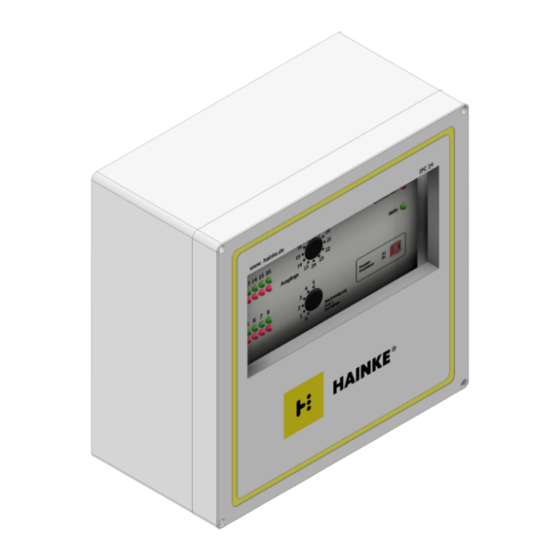
- Page 1 Operation manual Electronic solenoid valve control IFC 24 Version V1.0 · 04/2022...
- Page 2 Hainke Filteranlagen GmbH An der Imbäke 7 27798 Hude Germany Tel: +49 4408 8077-0 Fax: +49 4408 8077-100 Email: info@hainke.de Internet: www.hainke.de Electronic solenoid valve control · V1.0 · 04/2022 Operation manual...
-
Page 3: Table Of Contents
Notes on particular conditions for safe use in hazardous area Zone 22 ... 2 Intended use ......................3 Technical data ...................... 4 Assembly and installation ..................Electrical connection ..................Dimension plan IFC 24 ................... Connection plan IFC24 .................. 5 Start-up ......................... 6 Control and message functions ................Remote control input F .................. -
Page 4: Safety
• EN 55014-1:2012 • EN 60204-1:2012 • EN 60079-0:2014 • EN 60079-31:2014 The named standards and directives can be examined at HAINKE Filteranlagen GmbH . Marking electrical equipment for potentially explosive atmospheres Marking according to Dir- ective 2014/34/EU: II 3D... -
Page 5: Operation Of The Control In The Mounting Enclosure
2 | Intended use Areas of use Category 3 Zone 22 non-conductive dust Equipment group II Cat- Equipment designed to be capable of functioning in conformity egory 3D with the operating parameters established by the manufacturer and ensuring a normal level of protection. Electrical equipment for use Equipment in this category is intended for use in areas in which ex- in areas with combustible... -
Page 6: Technical Data
Quiescent current in- typically 45 mA typically 90 mA typically 60 mA Type IFC 24 in polyester mounting enclosure Output data 24 solenoid valve outputs 24 VDC, output power max. 24 W / 1 A Output fuse 1.6 A very fast acting 13 − 24 outputs manually activatable with a step switch. - Page 7 3 | Technical data Type IFC 24 in polyester mounting enclosure Conformity Low Voltage Directive 2014/35/EU (EN 60204-1) Directive 2014/30/EU Electromagnetic Compatibil- ity (EN 61000-6-1, EN 61000-6-2, EN 55014-1) Directive 2014/34/EU equipment and protective systems intended for use in potentially explosive atmospheres (EN 60079-0, EN 60079-31) Equipment marking II 3D tc IIIB T80°C Dc X IP65...
-
Page 8: Assembly And Installation
Target group Unless assigned otherwise, the assembly and installation are carried out by skilled per- sonnel of HAINKE Filteranlagen GmbH . Work on the electrical installation is only carried out by electrically skilled personnel. Work on live parts is not planned. -
Page 9: Electrical Connection
4 | Assembly and installation Polyester mounting en- The polyester enclosure is intended for mounting indoors and outdoors. Polyester is closure weather resistant, corrosion-proof, termite resistant and highly resistant to chemical media. If using in potentially explosive atmospheres, the notes required in these instructions must be complied with. -
Page 10: Dimension Plan
4 | Assembly and installation Dimension plan IFC 24 Electronic solenoid valve control · V1.0 · 04/2022 Operation manual... -
Page 11: Connection Plan
4 | Assembly and installation Connection plan IFC24 Operation manual Electronic solenoid valve control · V1.0 · 04/2022... -
Page 12: Start-Up
5 | Start-up Start-up WARNING Risk of injury due to the escape of a potentially explosive atmosphere consisting of dust/air mixtures ü Operation with the cover open is prohibited. 1. Before opening the cover, ensure that no potentially explosive atmosphere exists. 2. -
Page 13: Control And Message Functions
6 | Control and message functions 1. Check for correct actuation of the valves. In the event of error-free ac- tuation, the status message contact remains operated for the entire run. Light-emitting diode is lit without interruption. 1. Following completion of the commissioning, screw the cover back on, check the cable entries. -
Page 14: Secondary Cleaning
7 | Fault messages • Direct voltages 12 to 30 V, to 0 V The input is protected against reverse polarity. The function for testing the rated operating pressure is activated by DIP switch 2 in the On position, and is deactivated in the Off position. The switch may also be changed over while the control is in operation. - Page 15 7 | Fault messages Message Display Cause of error Remedy • If the compressed air is not to be monitored, set DIP switch 2 to the OFF position Operation manual Electronic solenoid valve control · V1.0 · 04/2022...
- Page 16 Keeping the World Flowing for Future Generations...

Need help?
Do you have a question about the IFC 24 and is the answer not in the manual?
Questions and answers