
Summary of Contents for Stat-X SOLO
- Page 1 SOLO Control Panel O&M Manual Version 0.4 Jan. 2014 Amendments: 1) Revision to test fuse rating options. 2) Revision of manual release test procedure. 3) Addition of Fault signaling capability.
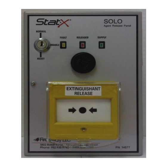
- Page 2 Audible/visual warning devices. The Solo panel has a 90dB internal fire and fault sounder built in. It is capable of driving a further single 12 VDC remote sounder. This circuit is monitored for open/closed circuit faults either of which will result in a common fault LED illuminating on the fascia of the panel and the internal buzzer will sound intermittently.
- Page 3 Fault signaling capability The fault output on the SOLO is an open collector type. This allows a relay coil or similar to be connected between the positive 12V terminal and the fault output 1/2014 Page 3 of 8 19020.4...
- Page 4 terminal. A diode must always be fitted to any relay coil to prevent any back EMF spikes from disrupting the microprocessor. It's fail-safe so the output is pulled down to approximately the same potential as the negative 12V terminal when no faults are present.
- Page 5 Initial power up The control panel is supplied with 2K7 end of line (EOL) in place across the sounder terminals, the Zone terminals and a 10K resistor across the battery terminals. A link should be placed in the EXT terminals so that the functionality of the control panel can be tested before any field wiring takes place.
- Page 6 Switch the panel mode key to “Normal” position with all the resistors and links in position and apply the 240V or 120V mains power to the control panel. The internal buzzer will sound momentarily and then the control panel should show the “Supply”...
- Page 7 Install a single rechargeable 1.2AH 12VDC sealed lead battery. (Auxiliary device dependent) Once installed and the control panel is tested “POWER DOWN” the control panel completely. Field wiring. Detection Install the fire detection circuits. The control panel is designed to operate with switching type detectors and will require a 470Ω...
- Page 8 Remove the link from the EXT terminal and replace with the actuation lead field wiring. (Polarity is not important). Place a 1 amp quick blow fuse in the test lead fuse holder. POWER UP the control panel and check that no faults exist on the installed circuits.
- Page 9 For further information or technical assistance please contact: Fireaway Inc. 5852 Baker Road Minnetonka, MN, 55345 Telephone: (1) 952-935-9745 Fax: (1) 952-935-9757 URL: www.statx.com 1/2014 Page 9 of 8 19020.4...
Need help?
Do you have a question about the SOLO and is the answer not in the manual?
Questions and answers