Table of Contents
Advertisement
Quick Links
FirePro
Xtinguish
Condensed Aerosol Fire Extinguishing System
Installation and Operation Manual
Hochiki America Corporation
7051 Village Drive, Suite 100
Version 1.05 - UL
Buena Park, CA 90621-2268
Created: 09/05/2012
714.522.2246 Corporate Headquarters
Revised: 11/17/2016
800.845.6692 Technical Support
http://www.hochiki.com
PN# 1700-11990
Read this installation and operation manual carefully before
installing the condensed aerosol generators!!
Advertisement
Table of Contents

Summary of Contents for Hochiki FirePro Xtinguish
- Page 1 FirePro Xtinguish Condensed Aerosol Fire Extinguishing System Installation and Operation Manual Hochiki America Corporation 7051 Village Drive, Suite 100 Version 1.05 - UL Buena Park, CA 90621-2268 Created: 09/05/2012 714.522.2246 Corporate Headquarters Revised: 11/17/2016 800.845.6692 Technical Support http://www.hochiki.com PN# 1700-11990...
-
Page 2: Table Of Contents
7.1.5 The Mounting Brackets: ........................18 7.1.6 The End Plate Discharge Outlets: ....................18 7.1.7 The Seal ............................18 7.2 Aerosol Generator Components......................19 Total Flooding Systems Design ......................... 21 Page 2 of 113 FirePro Xtinguish I&O Manual V1.05 UL... - Page 3 8.5.7 Generator Choice and Location......................26 8.6 Preparing the Enclosure Prior to Aerosol Discharge................26 8.7 Working in a Room or Enclosure Protected by FirePro Xtinguish ............26 Condensed Aerosol Fire Extinguishing System Arrangement ..............27 9.1 Minimum Safe Distances ......................... 27 9.2 Safety Requirements ..........................
- Page 4 11.2.2 FNX-40 / FNX-80 / FNX-100S / FNX-200S Installation Details ............39 11.2.3 FNX-500S Installation Details ......................39 11.3 Wiring Connections to the FirePro Xtinguish Aerosol Generators ............40 11.4 Condensed Aerosol Generator Height Limitations ................46 11.5 Condensed Aerosol Generator Initiation (Activation) ................46 11.5.1 Automatic Activation by means of a Fire Detection System ............
- Page 5 15.6 Waste and Environment ........................65 Appendix A – Material Safety Data Sheets (MSDS) ................66 Appendix B – FirePro Xtinguish Aerosol Generators ................70 Appendix C – FirePro Xtinguish Generator Datasheets ............... 71 Appendix D – FirePro Xtinguish Generator Drawings ................90 Appendix E –...
-
Page 6: Introduction
1 Introduction This manual is written for those who are installing a FirePro Xtinguish condensed aerosol fire extinguishing system for total flooding applications. Hochiki America Corporation assumes no responsibility for the application of any system other than those addressed in this manual. -
Page 7: Administration
Authorized Hochiki training is necessary and required to design, install, operate and maintain the FirePro Xtinguish system! Do not attempt to install or service this system if you have not been provided with authorized training! The requirements of this manual are considered necessary to provide a sufficient level of protection from loss of life and property from fire. -
Page 8: Environmental Summary
September 27, 2006/ Rules and Regulations. Under paragraph II, Listing Decisions: Fire Suppression and Explosion Protection – Total Flooding, at pages 56363/56364. C. Powdered Aerosol E – Acceptable subject to use conditions. Page 8 of 113 FirePro Xtinguish I&O Manual V1.05 UL... -
Page 9: Condensed Aerosol Environmental Parameters
Electrical conductivity Nil up to 75KV Negligible within the Corrosion parameters for use Extinguishing efficacy High Oxygen depletion after agent Negligible within the discharge parameters for use Page 9 of 113 FirePro Xtinguish I&O Manual V1.05 UL... -
Page 10: Safety Summary
Direct contact with the aerosol solid particles being discharged by the system can result in irritation of the eyes. Exposure of the condensed aerosol to the eyes should be avoided. Page 10 of 113 FirePro Xtinguish I&O Manual V1.05 UL... -
Page 11: Pre-Discharge Alarms And Time Delay
See the Material Safety Data Sheet contained in Appendix A and the information in section 3.2 of this manual. 4.2.6 Thermal Hazards FirePro Xtinguish condensed aerosol generators shall not be employed at less than the minimum safe distance from personnel and combustible materials. See the aerosol generator datasheets for minimum safe distance information. -
Page 12: Condensed Aerosol Fire Extinguishing Action
This physical theory had to be modified as halons became more widely used and better understood. The halons, as well as other agents like the FirePro Xtinguish condensed aerosol, do not extinguish fire in any of these ways, but instead break up the uninhibited chain reaction of the combustion process. -
Page 13: Firepro ® Condensed Aerosol Fire Extinguishing Reaction Sequence
5.1 FirePro Xtinguish Condensed Aerosol Fire Extinguishing Reaction Sequence Oxidation of hydrogen in the flames: → 2 OH → H O + H → OH → OH Oxidation of carbon monoxide in the flame: → 2 OH + CO → CO →... -
Page 14: Particle Distribution In The Aerosol Phase
5.2 Particle Distribution in the Aerosol Phase The FirePro Xtinguish condensed aerosol phase consists of a gas phase with micro sized solid particles in suspension. Laser beam diffraction tests analyses have shown the correlation between solid and gaseous components of 52% solid and 48% gas. -
Page 15: Firepro Xtinguish Condensed Aerosol Fire Use And Limitations
The above list may be not exhaustive. Contact Hochiki America Corporation or your local Hochiki America dealer if additional information is required. The FirePro Xtinguish condensed aerosol generators shall not be employed at less than the minimum safe distances specified in the present manual (see the aerosol generator datasheets for details). -
Page 16: Environmental Factors
Where unrelated extinguishing or suppression systems are provided, and can operate prior to, or during the hold time of the FirePro Xtinguish condensed aerosol extinguishing systems, the other agent shall not adversely affect the aerosol. -
Page 17: Condensed Aerosol Generator Description
7.1.2 The Ignition Device (Initiator): FirePro Xtinguish condensed aerosol generators are initiated by applying the appropriate voltage across the electric wire terminals of the aerosol generator so that the solid aerosol forming compound will be activated and transformed into the condensed aerosol (the extinguishing agent). -
Page 18: The Housing (External Steel Casing)
Mounting brackets are provided for each FirePro Xtinguish condensed aerosol generator, allowing the generator appropriate orientation. The mounting brackets are constructed by galvanized carbon steel plate of suitable shape and strength to hold the FirePro Xtinguish condensed aerosol generators. 7.1.6 The End Plate Discharge Outlets: The end plate discharge outlet holes ensure a smooth and fast discharge of the aerosol. -
Page 19: Aerosol Generator Components
7.2 Aerosol Generator Components FirePro Xtinguish Unit Components FirePro Xtinguish Unit Designations Page 19 of 113 FirePro Xtinguish I&O Manual V1.05 UL... - Page 20 FirePro Xtinguish Initiator (electrical activator) The initiator is connected to the activation power circuit (minimum current required 0.8 A for 3 - 4 seconds) by heat resistant wires. The activation power will heat up the electric coil (4) thus the (5) solid aerosol forming compound (FPC) will initiate an exothermal reaction.
-
Page 21: Total Flooding Systems Design
8 Total Flooding Systems Design 8.1 Working Documents The design of a FirePro Xtinguish condensed aerosol total flooding fire extinguishing system shall be prepared only by a person qualified and experienced in designing extinguishing systems, in accordance with the advice of the authority having jurisdiction. -
Page 22: Approval Of Plans
8.2 Enclosure In the design of a FirePro Xtinguish condensed aerosol total flooding fire extinguishing system, the integrity of the protected enclosure shall be considered. The area of non-closable openings in the protected enclosure shall be kept to a minimum. -
Page 23: Condensed Aerosol System Agent Supply
8.4 Design Application Density 8.4.1 Determining Design Application Density The FirePro Xtinguish condensed aerosol extinguishing application density shall be used in determining the minimum design application density for a particular fuel. For combinations of fuels, the extinguishment value for the fuel requiring the greatest condensed aerosol design application density shall be used, unless specific tests are made on the actual mixture. - Page 24 Class of Fire Extinguishing application Minimum design application density density 84 g/m 109.20 g/m Class B Fuels: 84 g/m 109.20 g/m Class A Fuels: 84 g/m 109.20 g/m Class C Fuel: Page 24 of 113 FirePro Xtinguish I&O Manual V1.05 UL...
-
Page 25: Total Flooding Quantity
8.5.2 Additional Design Factors In addition to the FirePro Xtinguish condensed aerosol agent quantity determined by the design application density, additional quantities of agent are required through the use of additional design factors to compensate for any special conditions that would affect the extinguishing efficiency. -
Page 26: Generator Choice And Location
To avoid or reduce the possibility of unwanted false aerosol discharge as a result of human error, it is important to disable the automatic detection network and/or isolate the FirePro Xtinguish system prior to the start of contractual work. The control panel will indicate the off-normal condition while the system is disabled. -
Page 27: Condensed Aerosol Fire Extinguishing System Arrangement
9.1 Minimum Safe Distances Minimum safe distances: FirePro Xtinguish condensed aerosol generators shall not be installed at less than the minimum safe distances as specified in the FirePro Xtinguish condensed aerosol generator data sheets. The generator datasheets are in Appendix C of this manual. -
Page 28: Electrical Clearances
The clearance between non insulated, energized parts of the electrical system equipment and any portion of the FirePro Xtinguish condensed aerosol extinguishing system shall not be less than the minimum clearance provided elsewhere for electrical system insulations on any individual component 9.4 Precautions While Handling the Generator Units... -
Page 29: Storage And Transport
The units shall be transported by ships and by airfreight in accordance with the regulations and requirements applicable to the above category of cargo. Transport by road of the FirePro Xtinguish condensed aerosol generators is permitted utilizing all types of transport vehicles without any restrictions. -
Page 30: Detection, Actuation, Alarm And Control Systems
All operating devices shall be UL listed and compatible with the control panel. The system actuation shall cause simultaneous operation of FirePro Xtinguish condensed aerosol generators. All devices/components shall be designed to be suitable for the specific intended service and working conditions. -
Page 31: Fire Alarm Control Panel
Audible and visual pre-discharge alarms shall be provided within the protected area to give positive warning of the impending discharge. The operation of the warning devices shall continue after FirePro Xtinguish condensed aerosol discharge, until positive action has been taken to acknowledge the alarm and proceed with appropriate action. -
Page 32: Abort Switches
To avoid unwanted discharge of an aerosol system during maintenance or when anyone enters the protected enclosure, a supervised disconnect switch shall be provided. The disconnect switch shall interrupt the releasing circuit to the FirePro Xtinguish condensed aerosol system. The disconnect switch shall be UL listed and compatible with the control panel. -
Page 33: Total Flooding System - Installation Examples
11 Total Flooding System – Installation Examples Figure 11.1 – Recommended FirePro Xtinguish condensed aerosol generator arrangement, ceiling Figure 11.2 – Recommended FirePro Xtinguish condensed aerosol generator arrangement, top of side walls Page 33 of 113 FirePro Xtinguish I&O Manual... - Page 34 Figure 11.3 – WRONG FirePro Xtinguish condensed aerosol arrangement The location of the generators shown above is incorrect. The generator outlets are pointing the aerosol stream in the direction of an opening. If the doors were left open at the time of generator activation, the aerosol would easily escape from the protected volume.
- Page 35 Page 35 of 113 FirePro Xtinguish I&O Manual V1.05 UL...
- Page 36 Page 36 of 113 FirePro Xtinguish I&O Manual V1.05 UL...
-
Page 37: General
The discharge outlets of the FirePro Xtinguish condensed aerosol generators shall not be obstructed. Minimum safe distances: FirePro Xtinguish condensed aerosol generators shall not be installed at less than the minimum safe distance as specified in the condensed aerosol generator data sheet. The generator datasheets are in Appendix C of this manual. -
Page 38: Firepro Condensed Aerosol Generator Installation Procedure
Complete all other connections to the fire alarm control panel. Apply power to the control panel when the installation is complete. On completion, ensure that the FirePro Xtinguish condensed aerosol generators have been installed in the correct manner, i.e. that all requirements contained in this manual have been accomplished. -
Page 39: Fnx-80 / Fnx-100S / Fnx-200S Installation Details
Installation of the FNX-1200 to FNX-5700 generators follows the same basic steps as those shown here. Secure the mounting bracket to the surface, and then attach the generator to the bracket. Always be sure to observe minimum safe distances (see Section 9.1). Page 39 of 113 FirePro Xtinguish I&O Manual V1.05 UL... -
Page 40: Wiring Connections To The Firepro Xtinguish Aerosol Generators
11.3 Wiring Connections to the FirePro Xtinguish Aerosol Generators Follow these steps to connect the generator to the extinguishing circuit: Step 1: Disassemble the aerosol generator into three parts; • Part 1 – the cable gland connector • Part 2 – the activator cable housing •... - Page 41 Mark 3 cm (1.18 in.) from point “A” to point “B”. Remove the shield of the cable from point “B” to the edge of the cable. c) Cut both wires 1.5 cm (0.59 in.) from point “B” to point “C”. Page 41 of 113 FirePro Xtinguish I&O Manual V1.05 UL...
- Page 42 Strip both wires so that approximately 4mm (0.16 in.) of the conductors are exposed. Point “C” to point “D”. e) Slice the jacket of the cable from point “B” to point “A” and remove the ground wire. The wire is now prepared for use. Page 42 of 113 FirePro Xtinguish I&O Manual V1.05 UL...
- Page 43 Step 3: Feed the prepared cable through the cable gland connector and the activator cable housing. Do not pass the ground wire through; leave it exposed on the outside of the cable gland connector as illustrated below. Page 43 of 113 FirePro Xtinguish I&O Manual V1.05 UL...
- Page 44 Step 5: While holding the cable in place to prevent it from turning, reattach the activator housing to the generator. Step 6: Put silicone inside of the cable gland connector in order to seal it. Page 44 of 113 FirePro Xtinguish I&O Manual V1.05 UL...
- Page 45 Step 7: Attach the cable gland connector to the activator cable housing. Connect the ground wire to the tab on the activator cable housing. Page 45 of 113 FirePro Xtinguish I&O Manual V1.05 UL...
-
Page 46: Condensed Aerosol Generator Height Limitations
11.5.1 Automatic Activation by means of a Fire Detection System A listed and compatible fire alarm control panel may be used to automatically activate the aerosol generator(s). Page 46 of 113 FirePro Xtinguish I&O Manual V1.05 UL... - Page 47 Manual Release Button (Hand-operated switch) Visual and/or Audible Notification Appliances Automatic fire alarm detectors Condensed Aerosol Generators Electrical Connection to Initiator Activator Module Disconnect Switch Figure 11.5.1 – Typical System Configuration Page 47 of 113 FirePro Xtinguish I&O Manual V1.05 UL...
-
Page 48: Hochiki Hcvr-3 Releasing Fire Alarm Control Panel
The HCVR-SQA Sequential Activator Module – this module is used to activate FirePro Xtinguish aerosol generators (g). Up to 20 HCVR-SQA modules may be used, with up to two (2) aerosol generators connected to each HCVR-SQA. - Page 49 Abort Switch (e) HCVR-3 Fire Alarm Control Panel (a) Extinguishing Generators (g) Extinguishing Generators (g) HCVR-SQA Sequential Activator Modules (d) Extinguishing Generators (g) Extinguishing Generators (g) Figure 12.1.1 – System Components Page 49 of 113 FirePro Xtinguish I&O Manual V1.05 UL...
-
Page 50: System Layout
Install the HCVR-3 control panel, initiating devices, notification appliances, FirePro Xtinguish aerosol generators, and all other equipment as stated on the design plans. Always check with the system designer in the event of questions;... -
Page 51: Hcvr-3 Connection Overview
If only one HCVR-SQA is used, install the jumper on the module. In summary, one HCVR-SQA module shall have the jumper installed and it must always be the last module on the circuit, even if only one module is used. Page 51 of 113 FirePro Xtinguish I&O Manual V1.05 UL... - Page 52 NOTE: the maximum impedance for the EXTING circuit is 9.7 ohms. Figure 12.3.2 – Wiring Diagram for the HCVR-SQA Page 52 of 113 FirePro Xtinguish I&O Manual V1.05 UL...
- Page 53 Measure the resistance of the circuit where the wire connects to the HCVR-3 EXTING circuit. Ensure that the resistance is 9.7 ohms or less. Page 53 of 113 FirePro Xtinguish I&O Manual V1.05 UL...
- Page 54 Do not measure the circuit with the generators connected. The generators will introduce additional resistance into the circuit and will affect the accuracy of your measurement. See the HCVR-SQA Sequential Activator Installation Sheet for additional details. Page 54 of 113 FirePro Xtinguish I&O Manual V1.05 UL...
-
Page 55: Disconnect Switch (Hochiki America Model Hcvr-Ds Or Som-R-Ds)
12.3.3 Disconnect Switch (Hochiki America model HCVR-DS or SOM-R-DS) To comply with NFPA requirements, a Disconnect Switch (model HCVR-DS or SOM-R-DS) may be installed in the EXTING circuit. The purpose of this switch is to help prevent accidental activation of the aerosol generators during testing and maintenance of the system. -
Page 56: Elan Rs-H Analog/Addressable Releasing Control Panel
Modules Additional SLC Devices For additional details regarding installation, programming and operation of the eLAN RS-H panel, please see the eLAN Installation Manual, document # VF3528-00 (revision E01.13 or higher). Page 56 of 113 FirePro Xtinguish I&O Manual V1.05 UL... -
Page 57: Total Flooding System Commissioning
The FirePro Xtinguish condensed aerosol generators shall be securely fastened to prevent unacceptable vertical or lateral movement during discharge. The FirePro Xtinguish condensed aerosol generators shall be oriented in such a manner that optimum agent dispersal can be effected. The FirePro Xtinguish condensed aerosol generator stream shall not directly impinge on areas where personnel may be located. - Page 58 Manual pull stations shall be installed, readily accessible, accurately identified, and protected to prevent damage. All manual stations used to release agents shall require two separate and distinct actions for operation. All manual stations used to release the FirePro Xtinguish condensed aerosol system shall be identified. Particular...
-
Page 59: Functional Testing
Notify all concerned personnel at the facility that a test is to be conducted. Instruct personnel as to the sequence of operation. Disable the FirePro Xtinguish condensed aerosol system actuation mechanism so that activation of the release circuit will not actuate the FirePro Xtinguish condensed aerosol generators. Check each detector for response. -
Page 60: System Hand-Over To Client
The condensed aerosol system shall be returned to its fully operational design condition. The central station and all concerned personnel at the end-user's facility shall be notified that the FirePro Xtinguish condensed aerosol fire system test is complete and that the system has been returned to full service condition. -
Page 61: Total Flooding Systems Inspection And Maintenance
(NFPA 2010 2015 Edition, 9.1.2.1) 14.2 Enclosure Inspection At least every 12 months, the enclosure protected by the FirePro Xtinguish condensed aerosol fire system shall be thoroughly inspected to determine if penetrations or other changes have occurred that could adversely affect agent leakage or change volume of hazard or both. -
Page 62: Training
14.6 Training All persons who could be expected to inspect, test, maintain, or operate the FirePro Xtinguish condensed aerosol fire extinguishing system shall be thoroughly trained and kept thoroughly trained in the functions they are expected to perform. Personnel working in an enclosure protected by a FirePro Xtinguish condensed aerosol fire system shall receive training regarding agent safety issues. -
Page 63: Total Flooding System Post-Discharge Intervention
If the FirePro Xtinguish condensed aerosol particles (dust) remain for a longer period, they will absorb moisture. The moisture will react with metals (especially uncoated metals), causing oxidation to occur. -
Page 64: Pre-Discharge And Post-Discharge Steps
15.3 Pre-Discharge and Post-Discharge Steps The following steps are necessary prior to discharge of the FirePro Xtinguish aerosol: • HVAC systems must be shut down. This allows the aerosol to reach the fire as quickly as possible. May be automatically controlled by the fire alarm panel. -
Page 65: Condensed Aerosol Generators
15.6 Waste and Environment After activation the FirePro Xtinguish condensed aerosol generators may be disposed of as normal waste after dismantling. If a condensed aerosol generator has been removed from service but it has not been activated and it still contains the solid aerosol-forming compound FPC, the generator must be returned to Hochiki America Corporation for proper disposal. -
Page 66: Appendix A - Material Safety Data Sheets (Msds)
: Remove from exposure area to fresh air. Eye Contact : If necessary wash eyes. Skin Contact : Change clothing and shoes. Wash skin with soap. Ingestion : Not likely. Page 66 of 113 FirePro Xtinguish I&O Manual V1.05 UL... - Page 67 : None known Hazardous Reactions : Will not occur 10.2 Conditions to avoid : None known 10.3 Materials to Avoid : None known 10.4 Hazardous Decompositions Products : None ascertained Page 67 of 113 FirePro Xtinguish I&O Manual V1.05 UL...
- Page 68 13.1 Dispose of in Compliance with local, state and national regulations. Transportation Information : 9 miscellaneous, solid 14.1 Hazard Class or Division : For additional transport information contact Hochiki America Corporation Page 68 of 113 FirePro Xtinguish I&O Manual V1.05 UL...
- Page 69 17.1 The data in the above material safety data sheet reflect the current state of knowledge of our product and shall be used only as a guideline. No binding statements as to the contractually agreed product characteristics may be inferred there from. Page 69 of 113 FirePro Xtinguish I&O Manual V1.05 UL...
-
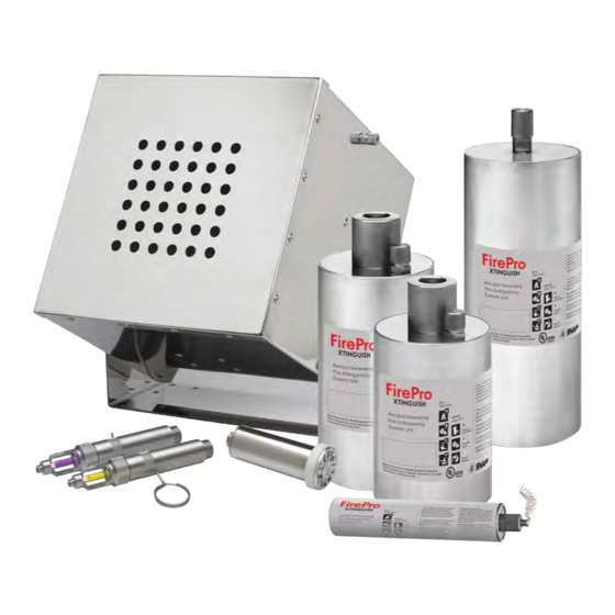
Page 70: Appendix B - Firepro Xtinguish Aerosol Generators
17 Appendix B – FirePro Xtinguish Aerosol Generators FNX-20S / FNX-20T FNX-40S / FNX-40T FNX-80S / FNX-80T FNX-100S FNX-200S FNX-500S FNX-1200 FNX-2000 FNX-3000 FNX-1200T FNX-2000T FNX-3000T FNX-1200S FNX-2000S FNX-3000S FNX-1200TS FNX-2000TS FNX-3000TS FNX-5700 FNX-4200T FNX-5700T FNX-4200TS FNX-5700S FNX-5700TS... -
Page 71: Appendix C - Firepro Xtinguish Generator Datasheets
Appendix C – FirePro Xtinguish Generator Datasheets... - Page 72 Page 72 of 113 FirePro Xtinguish I&O Manual V1.05 UL...
- Page 73 FirePro Xtinguish - Height of Installation and Minimum Clearances Distance from Distance from generator generator outlet (ft.) outlet (m) 1.2192 0.9144 0.6096 0.3048 FNX-20S FNX-40S FNX-80S 0.3048 0.6096 0.9144 1.2192 0'-0" 0'-0" 0'-0" Min. Distance to Combustibles 0'-4" 0'-4" 0'-4"...
- Page 74 0'-0" 0'-3.937" 0'-0" 0'-0" 0.1m Min. Distance to Combustibles 0'-0" 0'-7.874" 0'-11.81" 7'-2.614" 0'-0" 0'-0" 0.2m 0.3m 0.5m Min. Distance to Personnel 6'-6.740" 3'-3.37" 6'-6.740" 6'-6.740" 3'-3.37" 3'-3.37" Stream Length Page 74 of 113 FirePro Xtinguish I&O Manual V1.05 UL...
- Page 75 11'-5.795" 3.5m 3.5m 3.5m Stream Length 4.572 4.8768 3'-2.976" 0.99m 1'-11.622" 0.6m Min. Distance to Combustibles 7'-6.551" 6'-6.74" 2.3m 2.0m Min. Distance to Personnel 16'-4.850" 27'-6.708" 5.0m 8.4m Stream Length Page 75 of 113 FirePro Xtinguish I&O Manual V1.05 UL...
- Page 76 FirePro Xtinguish Condensed Aerosol generators: FNX-20S FNX-20S LEGEND Maximum height of installation Minimum clearance from persons Minimum clearance from combustible materials Technical Data 20 g (Aerosol Generating Solid Compound) Mass of FPC Weight Tolerance Generator gross weight 310 g ± 5% Activation mode Electrical 6/12/24/36 V D/C 0.8 A 3-4 s...
- Page 77 Oxygen depletion After Electrical conductivity Technical Parameters discharge Nil up to 75KV Negligible ODP: Ozone Depletion Potential ALT: Atmospheric Life Time Notes GWP: Global Warming Potential Within the parameters for use Page 77 of 113 FirePro Xtinguish I&O Manual V1.05 UL...
- Page 78 Oxygen depletion After Electrical conductivity Technical Parameters discharge Nil up to 75KV Negligible ODP: Ozone Depletion Potential ALT: Atmospheric Life Time Notes GWP: Global Warming Potential Within the parameters for use Page 78 of 113 FirePro Xtinguish I&O Manual V1.05 UL...
- Page 79 Oxygen depletion After Electrical conductivity discharge Technical Parameters Nil up to 75KV Negligible ODP: Ozone Depletion Potential ALT: Atmospheric Life Time Note GWP: Global Warming Potential Within the parameters for use Page 79 of 113 FirePro Xtinguish I&O Manual V1.05 UL...
- Page 80 Oxygen depletion After Electrical conductivity discharge Technical Parameters Nil up to 75KV Negligible ODP: Ozone Depletion Potential ALT: Atmospheric Life Time Notes GWP: Global Warming Potential Within the parameters for use Page 80 of 113 FirePro Xtinguish I&O Manual V1.05 UL...
- Page 81 Oxygen depletion After Electrical conductivity discharge Technical Parameters Nil up to 75KV Negligible ODP: Ozone Depletion Potential ALT: Atmospheric Life Time Note GWP: Global Warming Potential Within the parameters for use Page 81 of 113 FirePro Xtinguish I&O Manual V1.05 UL...
- Page 82 Oxygen depletion After Electrical conductivity discharge Technical Parameters Nil up to 75KV Negligible ODP: Ozone Depletion Potential ALT: Atmospheric Life Time Note GWP: Global Warming Potential Within the parameters for use Page 82 of 113 FirePro Xtinguish I&O Manual V1.05 UL...
- Page 83 Oxygen depletion After Electrical conductivity discharge Technical Parameters Nil up to 75KV Negligible ODP: Ozone Depletion Potential ALT: Atmospheric Life Time Note GWP: Global Warming Potential Within the parameters for use Page 83 of 113 FirePro Xtinguish I&O Manual V1.05 UL...
- Page 84 Oxygen depletion After Electrical conductivity discharge Technical Parameters Nil up to 75KV Negligible ODP: Ozone Depletion Potential ALT: Atmospheric Life Time Note GWP: Global Warming Potential Within the parameters for use Page 84 of 113 FirePro Xtinguish I&O Manual V1.05 UL...
- Page 85 Oxygen depletion after Electrical Conductivity discharge Technical Parameters Nil up to 75KV Negligible ODP: Ozone Depletion Potential ALT: Atmospheric Lifetime Notes GWP: Global Warming Potential Within the parameters for use Page 85 of 113 FirePro Xtinguish I&O Manual V1.05 UL...
- Page 86 Oxygen depletion after Electrical Conductivity Technical Parameters discharge Nil up to 75KV Negligible ODP: Ozone Depletion Potential ALT: Atmospheric Lifetime Notes GWP: Global Warming Potential Within the parameters for use Page 86 of 113 FirePro Xtinguish I&O Manual V1.05 UL...
- Page 87 Oxygen depletion after discharge Technical Parameters Nil up to 75KV Negligible ODP: Ozone Depletion Potential 3 ALT: Atmospheric Lifetime Notes GWP: Global Warming Potential 4 Within the parameters for use Page 87 of 113 FirePro Xtinguish I&O Manual V1.05 UL...
- Page 88 Oxygen depletion After Electrical conductivity discharge Technical Parameters Nil up to 75KV Negligible ODP: Ozone Depletion Potential ALT: Atmospheric Life Time Note GWP: Global Warming Potential Within the parameters for use Page 88 of 113 FirePro Xtinguish I&O Manual V1.05 UL...
- Page 89 Oxygen depletion After Electrical conductivity Technical Parameters discharge Nil up to 75KV Negligible ODP: Ozone Depletion Potential ALT: Atmospheric Life Time Note GWP: Global Warming Potential Within the parameters for use Page 89 of 113 FirePro Xtinguish I&O Manual V1.05 UL...
-
Page 90: Appendix D - Firepro Xtinguish Generator Drawings
19 Appendix D – FirePro Xtinguish Generator Drawings Xtinguish FNX-20S... - Page 91 FNX-20T Page 91 of 113 FirePro Xtinguish I&O Manual V1.05 UL...
- Page 92 FNX-40S Page 92 of 113 FirePro Xtinguish I&O Manual V1.05 UL...
- Page 93 FNX-80S Page 93 of 113 FirePro Xtinguish I&O Manual V1.05 UL...
- Page 94 FNX-40T FNX-80T Page 94 of 113 FirePro Xtinguish I&O Manual V1.05 UL...
- Page 95 FNX-40T FNX-80T Page 95 of 113 FirePro Xtinguish I&O Manual V1.05 UL...
- Page 96 ELECTRICAL ACTUATOR FNX-100S Page 96 of 113 FirePro Xtinguish I&O Manual V1.05 UL...
- Page 97 ELECTRICAL ACTUATOR FNX-200S Page 97 of 113 FirePro Xtinguish I&O Manual V1.05 UL...
- Page 98 ELECTRICAL ACTUATOR FNX-500S Page 98 of 113 FirePro Xtinguish I&O Manual V1.05 UL...
- Page 99 FNX-100S FNX-200S Xtinguish FNX-500S Page 99 of 113 FirePro Xtinguish I&O Manual V1.05 UL...
- Page 100 FNX-1200 Xtinguish FNX-1200S Page 100 of 113 FirePro Xtinguish I&O Manual V1.05 UL...
- Page 101 FNX-1200T Xtinguish FNX-1200TS Page 101 of 113 FirePro Xtinguish I&O Manual V1.05 UL...
- Page 102 FNX-2000 Xtinguish FNX-2000S Page 102 of 113 FirePro Xtinguish I&O Manual V1.05 UL...
- Page 103 FNX-2000T Xtinguish FNX-2000TS Page 103 of 113 FirePro Xtinguish I&O Manual V1.05 UL...
- Page 104 FNX-3000 Xtinguish FNX-3000S Page 104 of 113 FirePro Xtinguish I&O Manual V1.05 UL...
- Page 105 FNX-3000T Xtinguish FNX-3000TS Page 105 of 113 FirePro Xtinguish I&O Manual V1.05 UL...
- Page 106 FNX-4200T Xtinguish FNX-4200TS Page 106 of 113 FirePro Xtinguish I&O Manual V1.05 UL...
- Page 107 FNX-5700 Xtinguish FNX-5700S Page 107 of 113 FirePro Xtinguish I&O Manual V1.05 UL...
- Page 108 FNX-5700T Xtinguish FNX-5700TS Page 108 of 113 FirePro Xtinguish I&O Manual V1.05 UL...
-
Page 109: Appendix E - Referenced Publications
20 Appendix E – Referenced Publications NFPA National Fire Protection Association, 1 Batterymarch Park, Quincy, MA 02169-7471 NFPA 2010 Standard for Fixed Aerosol Fire Extinguishing Systems, 2015 Edition NFPA 70 National Electrical Code ® , 2005 Edition NFPA 72 National Fire Alarm Code ®... -
Page 110: Appendix F - Definitions
An extinguishing medium consisting of finely divided solid particles, generally less than 10 microns in diameter, and gaseous matter, generated by a combustion process of a solid aerosol-forming compound. 21.10 - Coolant. A heat-absorbing medium or process. Page 110 of 113 FirePro Xtinguish I&O Manual V1.05 UL... - Page 111 Work performed to ensure that equipment operates as directed by the manufacturer. 21.22 - Manual. Requiring intentional intervention to accomplish a function. 21.23 - Normally Occupied. An area or space where, under normal circumstances, persons are present. Page 111 of 113 FirePro Xtinguish I&O Manual V1.05 UL...
- Page 112 A bulkhead or deck designed to resist the passage of smoke and flame for 1 hour, including limiting the temperature rise on the unexposed side to 180° C (325° F). 21.36 - Heat-Sensitive Material. A material whose melting point is below 1700°F (926.7°C). [13, 2002] Page 112 of 113 FirePro Xtinguish I&O Manual V1.05 UL...
- Page 113 A vessel operated on the navigable waterways of the United States that is subject to the regulations in 46 CFR Subchapter C, Parts 24 - 28, including pleasure craft, tugboats, towing vessels and certain fishing vessels. Page 113 of 113 FirePro Xtinguish I&O Manual V1.05 UL...
Need help?
Do you have a question about the FirePro Xtinguish and is the answer not in the manual?
Questions and answers