Table of Contents
Advertisement
Quick Links
Advertisement
Table of Contents

Summary of Contents for FireFlex FLX-PC
- Page 1 ® Vacuum / Pressure Controller Model FLX-PC Operation Manual FM-060M-0-84B...
- Page 2 Page ii ® FLX-PC Vacuum / Pressure Controller Operation Manual Systems Inc. Manufactured by 1935. Lionel-Bertrand Blvd Boisbriand, Quebec (Canada) J7H 1N8 Tel: (450) 437-3473 Toll free: (866) 347-3353 Fax: (450) 437-1930 info@fireflex.com Web Site: http://www.fireflex.com - E-Mail: FM-060M-0-84B...
- Page 3 Page iii ® FLX-PC Vacuum / Pressure Controller Operation Manual Table of Contents General Description ............................1 Display in Normal Condition ......................... 1 LCD Display Intensity Vacuum Pump Control ..........................2 Supervisory Pressure Forced Shutdown Reset Low and High Pressure ..........................2 Alarm Pressure ..............................
- Page 4 ® is a registered trade mark from F Systems Inc. FLX-PC ® is a registered trade mark from F Systems Inc.
-
Page 5: General Description
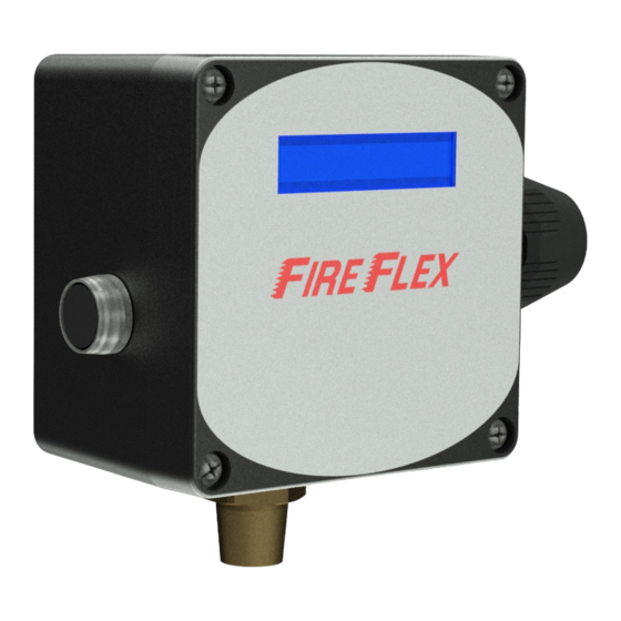
PRESSURE TRANSDUCER 1/2-NPT CONNECTION TOWARDS PIPING FM-061H-2-8A Figure 1 - Internal arrangement of the FLX-PC unit Display in Normal Condition In the attached example, we can see that the pump starts The system pressure is displayed in real time on the first line... -
Page 6: Operation Mode
When the pump is in operation, the sign [] appears to the Alarm Pressure right of the first line. Note: The vacuum pump will not operate if a trouble Note: This section do not applies to vacuum single interlock condition is present on the FLX-PC ® unit. pre-action systems. Forced Shutdown An alarm pressure signal is transmitted to release control panel when the vacuum level reaches -0.130 BAR. -
Page 7: Trouble Condition
Once the unit has been selected, the display will Events History Log automatically return to its normal condition after 10 seconds of inactivity of the push-button; the change of units will be The last 50 events are kept inside the FLX-PC ® unit for completed. -
Page 8: Electrical Wiring
Page 4 ® FLX-PC Vacuum / Pressure Controller Operation Manual Electrical Wiring panel through dry contacts of the FLX-PC ® unit. Control The electrical connections to the FLX-PC ® unit are rooted to contacts of the system come from the devices of the fire the release control panel via a built-in junction box and protection system.
Need help?
Do you have a question about the FLX-PC and is the answer not in the manual?
Questions and answers