
Summary of Contents for RSP P0010A
- Page 1 Product Manual m0403 Small valve unit M0001-1 Tool changers | Swivels | Swivel tool changers | Grippers | Hose packages | Valve units | Tool systems...
- Page 2 M0001-1 version 2.0...
- Page 3 The information in this document is subject to change without prior notice and should not be regarded as an undertaking from Robot System Products AB. Robot System Products AB assumes no responsibility for errors that may occur in this document. Robot System Products AB bears no responsibility for damage that is incurred by the use of this document, or the software or hardware described in this document.
-
Page 4: Table Of Contents
1.1.2 Explanation of warnings ..................... 7 2 TECHNICAL SPECIFICATIONS ................8 2.1 Description of RSP small, and extended, valve units ..........8 2.1.1 Small valve units: P0010A, P0012A and P0013A ............10 2.1.2 Small valve unit for tool changing and two valves: P0011A ..........11 2.1.3 Small valve unit without valves, no tool changing: P1008 .......... - Page 5 6 SPARE PARTS ..................... 38 6.1 Valve units without tool change, P0010A, P0012A and P0013A ....... 38 6.2 Valve units with tool change, P0011A ..............39 6.3 Extended units without tool change, P0035, P0036 and P0037 ........ 40 6.4 Extended units with tool change, P0026, P0027, P0028 and P0029 ......41 7 DISPOSAL AND RECYCLING ................
-
Page 6: Introduction
With RSP’s cost-effective CiRo, cables and hoses can be freely selected with high robot flexibility maintained, and space requirements reduced. Our integrated Tool systems are delivered as complete plug-and-play solutions designed for quick and simple installation. -
Page 7: Safety
1.1 Safety 1.1.1 General The integrator installing the valve unit must follow the safety demands stated in standards and provisions applicable in the country where the valve unit is to be installed. The user of the Robot System Products valve unit is responsible that law and directives applicable in respective countries, with regards to safety, are followed. -
Page 8: Technical Specifications
TECHNICAL SPECIFICATIONS 2.1 Description of RSP small, and extended, valve units This document presents the Robot System Products’ small valve and extended small valve units, ready for installation on the robot, available in different versions depending on required function. Valve units without tool change functions consists of between one and five electrically controlled monostable 5/2 valves, depending on configuration. - Page 9 Product overview extended small valve units Article number P0026 (section 2.1.4) P0027 (section 2.1.4) Description Valve unit without valves For tool changing and one valve Article number P0028 (section 2.1.4) P0029 (section 2.1.4) Description For tool changing and three valves For tool changing and four valves Article number P0035 (section 2.1.5)
-
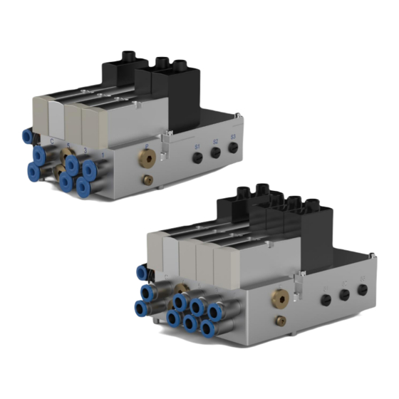
Page 10: Small Valve Units: P0010A, P0012A And P0013A
M12 8P A-coded – M12 8S (3 meter) I0650 (cable) M12 8P A-coded – (2 meter, 0.25 mm I0219 (cable) , open end) NOTE! P0010A is prepared for one tool change valve and up to three directional valves. M0001-1 version 2.0... -
Page 11: Small Valve Unit For Tool Changing And Two Valves: P0011A
2.1.2 Small valve unit for tool changing and two valves P0011A Technical data Article number P0011A +10°C−+50°C Working temperature Weight 1.1 kg Tool change valve channels Directional valves Valve size ISO02 18 mm IE, (ISO15407-2) Outlet channels Inlet channels Max air pressure 10 bar Air flow 550l /min for each valve... -
Page 12: Small Valve Unit Without Valves, No Tool Changing: P1008
2.1.3 Small valve unit without valves, no tool changing P1008 Technical data Article number P1008 +10°C−+50°C Working temperature Weight 0.9 kg Tool change valve channels Directional valves Valve size ISO02 18 mm IE, (ISO15407-2) Outlet channels max 8 Inlet channels Max air pressure 10 bar Air flow... -
Page 13: Extended Small Valve Units For Tool Changing: P0026, P0027, P0028 And P0029
2.1.4 Extended s mall valve units for tool changing P0026, P0027 P0028 P0029 Technical data Article number P0026 P0027 P0028 P0029 +10°C−+50°C Working temperature Weight 1.1 kg 1.4 kg 1.5 kg 1.5 kg Tool change valve channels Directional valves Valve size ISO02 18mm IE, (ISO15407-2) Outlet channels max 10... -
Page 14: Extended Small Valve Units: P0035, P0036 And P0037
2.1.5 Extended s : P0035 P0036 P0037 mall valve units Technical data Article number P0035 P0036 P0037 +10°C−+50°C Working temperature Weight 1.4 kg 1.5 kg 1.5 kg Tool change valve channels Directional valves Valve size ISO02 18mm IE, (ISO15407-2) Outlet channels Inlet channels Max air pressure 10 bar... -
Page 15: Pneumatic Diagrams
(section 2.2.4) P0013A NOTE! Valves are not included in P0010A and P1008. P0010A are intended for installation of up to three directional valves and one tool change valve. P1008 are intended for installation of four valves when no tool change function is required. -
Page 16: Pne0214-010 For Small Valve Unit P0010A
2.2.1 Pne0214-010 for small valve unit P0010A M0001-1 version 2.0... -
Page 17: Pne0214-011 For Small Valve Unit P0011A
2.2.2 Pne0214-011 for small valve unit P0011A M0001-1 version 2.0... -
Page 18: Pne0214-008 For Small Valve Unit P1008
2.2.3 Pne0214-008 for small valve unit P1008 M0001-1 version 2.0... -
Page 19: Pne0214-013 For Small Valve Units P0012A And P0013A
2.2.4 Pne0214-013 for small valve units P0012A and P0013A M0001-1 version 2.0... -
Page 20: Pne0214-026 For Extended Valve Unit P0026
2.2.5 Pne0214-026 for extended valve unit P0026 M0001-1 version 2.0... -
Page 21: Pne0214-027 For Extended Valve Units P0027, P0028 And P0029
2.2.6 Pne0214-027 for extended valve units P0027, P0028 and P0029 M0001-1 version 2.0... -
Page 22: Pne0214-035 For Extended Valve Units P0035 And P0036
2.2.7 Pne0214-035 for extended valve units P0035 and P0036 M0001-1 version 2.0... -
Page 23: Pne0214-037 For Extended Valve Unit P0037
2.2.8 Pne0214-037 for extended valve unit P0037 M0001-1 version 2.0... -
Page 24: Internal Circuit Diagrams
2.3 Internal circuit diagrams 2.3.1 E0214-167 for small valve units M0001-1 version 2.0... -
Page 25: E0214-222 For Extended Small Valve Units
2.3.2 E0214-222 for extended small valve units M0001-1 version 2.0... -
Page 26: Options
3 OPTIONS 3.1 Sensor interface, P1033 and P1018 for small valve units Electric interface for transfer of sensor signals to the robot, including three M8 3P or M8 4P contacts, which are added at the side of the valve unit and connected inside the unit. NOTE! The sensor interfaces P1033 or P1018 shall be ordered at the same time as the small valve unit and will pre-mounted on delivery. -
Page 27: Sensor Interface, P1032 For Extended Small Valve Unit
3.2 Sensor interface, P1032 for extended small valve unit Electric interface for transfer of sensor signals to the robot, including three M8 4P contacts, which are added at the side of the valve unit and connected inside the unit. NOTE! The sensor interface P1032 shall be ordered at the same time as the extended small valve unit and will pre-mounted on delivery. -
Page 28: Circuit Diagram E0214-306 For Sensor Interface P1033
3.3 Circuit diagram E0214-306 for sensor interface P1033 M0001-1 version 2.0... -
Page 29: Circuit Diagram E0214-263 For Sensor Interface P1018 And P1032
3.4 Circuit diagram E0214-263 for sensor interface P1018 and P1032 M0001-1 version 2.0... -
Page 30: Installation
4 INSTALLATION 4.1 Tightening torques Tightening torques for mounting (screw class 8.8) Dimension Torque 3 Nm 6 Nm 10 Nm 24 Nm 47 Nm 82 Nm 200 Nm 4.2 Recommended tools for installation and replacement of valve units Tools Applications Complete set of Allen keys For dismounting and mounting. -
Page 31: Installation Of Valve Unit On Robot
Connect robot cable If the cable connecting the valve unit and the robot is not supplied and preinstalled by RSP see section 4.5 Connect customer cable below. NOTE! If the cable is supplied by RSP it is already preinstalled on the valve unit. - Page 32 (sections 2.3.1 or 2.3.2). NOTE! If complete cable and hose packages are supplied by RSP the electrical cable on the tool side is preinstalled by RSP on the valve unit. Connect air supply hose Connect the air supply hose according to pneumatic diagram (section 2.2).
-
Page 33: Connect Customer Cable
4.5 Connect customer cable Action Note Remove all valves. Unscrew the, eight or ten, M3x30 screws holding the valves. Remove all valves and cover plates. Remove cover Unscrew the four M3x10 screws holding the cover and remove it. Terminals X1 and X2 are now available for connection. - Page 34 Mount cover Remount the cover with the four M3x10 screws. Check that the O-ring is in right position before tightening the screws. Mount valves Remount the valves. Ensure that there is no leakage at the valves. M0001-1 version 2.0...
-
Page 35: Maintenance And Service
5 MAINTENANCE AND SERVICE 5.1 Maintenance chart The valve units must be maintained regularly to ensure proper function. The specified intervals are approximate and valid under normal conditions. Under extreme conditions, such as dirty environments or extreme robot movements, the intervals should be shortened. Consider the table as a guide and update as the production experience of each system increases. -
Page 36: Replacement Of Valve Unit
5.3 Replacement of valve unit Action Note Safety Read the safety section 1.1. Service position Place the robot in service position. Power off Switch the power off and lock the circuit breaker. NOTE! Read the safety chapter for the robot. Pneumatic air off Switch the pneumatic air off. - Page 37 Disconnect air hoses at tool side Disconnect the air hoses between the valve unit and the tool. NOTE! Check that hoses are marked according to connections at the valve unit in both ends. NOTE! Ensure that no dirt enters the hoses or connectors.
-
Page 38: Spare Parts
6 SPARE PARTS 6.1 Valve units without tool change, P0010A, P0012A and P0013A Item Description Part number Hose connection 8 mm angled I0314 Hose connection 6 mm straight (P0012A only) I0354 Hose connection 6 mm straight (P0013A only) I0354 Cover plate (P0012A only) -
Page 39: Valve Units With Tool Change, P0011A
6.2 Valve units with tool change, P0011A Item Description Part number Hose connection 8 mm angled I0314 Hose connection 6 mm straight I0354 Cover plate I0492 Valve 5/2 monostable I0520 M0001-1 version 2.0... -
Page 40: Extended Units Without Tool Change, P0035, P0036 And P0037
6.3 Extended units without tool change, P0035 P0036 P0037 Item Description Part number Hose connection 8 mm straight (P0035 only) I0371 Hose connection 8 mm straight (P0036 only) I0371 Hose connection 8 mm straight (P0037 only) I0371 Valve 5/2 monostable (P0035 only) I0520 Valve 5/2 monostable (P0036 only) I0520... -
Page 41: Extended Units With Tool Change, P0026, P0027, P0028 And P0029
6.4 Extended units with tool change, P0026, P0027 P0028 P0029 Item Description Part number Hose connection 8 mm straight (P0027 only) I0371 Hose connection 8 mm straight (P0028 only) I0371 Hose connection 8 mm straight (P0029 only) I0371 Valve 5/2 monostable (P0027 only) I0520 Valve 5/2 monostable (P0028 only) I0520... -
Page 42: Disposal And Recycling
7 DISPOSAL AND RECYCLING Taking care of spent equipment Used equipment must be taken care of in an environmentally-friendly way. When disposed of, a major share of the material, or its energy content, can be recycled. The quantities possible to recycle vary depending on technical resources and practises in respective country. - Page 43 M0001-1 version 2.0...
- Page 44 M0001-1 version 2.0...
Need help?
Do you have a question about the P0010A and is the answer not in the manual?
Questions and answers