Table of Contents
Advertisement
Quick Links
CAN-Repeater
Passive I- and Y-Repeater for CAN
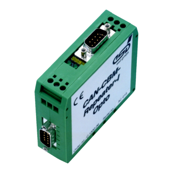
CAN-Repeater-I-Opto
(C.1330.06)
Hardware Manual
to Product C.1330.02, C.1330.03,
C.1330.06, C.1330.07
CAN-Repeater
Hardware Manual • Doc. No.: C.1330.21 / Rev. 1.5
Page 1 of 28
esd electronic system design gmbh
Vahrenwalder Str. 207 • 30165 Hannover • Germany
http://www.esd.eu
Phone: +49 (0) 511 3 72 98-0 • Fax: +49 (0) 511 3 72 98-68
Advertisement
Table of Contents

Related Manuals for ESD CAN-Repeater-I

Summary of Contents for ESD CAN-Repeater-I
- Page 1 CAN-Repeater Hardware Manual • Doc. No.: C.1330.21 / Rev. 1.5 Page 1 of 28 esd electronic system design gmbh Vahrenwalder Str. 207 • 30165 Hannover • Germany http://www.esd.eu Phone: +49 (0) 511 3 72 98-0 • Fax: +49 (0) 511 3 72 98-68...
- Page 2 The information in this document has been carefully checked and is believed to be entirely reliable. esd makes no warranty of any kind with regard to the material in this document, and assumes no responsibility for any errors that may appear in this document. In particular descriptions and technical data specified in this document may not be constituted to be guaranteed product features in any legal sense.
- Page 3 Document file: I:\Texte\Doku\MANUALS\CAN\Repeat\Englisch\CAN-Repeater_Hardware_en_15.odt Date of print: 2022-08-04 Document type DOC0800 number: Hardware version: XREPD01 Document History The changes in the document listed below affect changes in the hardware as well as changes in the description of the facts, only. Rev. Chapter Changes versus previous version Date...
- Page 4 Classification of Warning Messages and Safety Instructions This manual contains noticeable descriptions, warning messages and safety instructions, which you must follow to avoid personal injuries or death and property damage. This is the safety alert symbol. It is used to alert you to potential personal injury hazards. Obey all safety messages and instructions that follow this symbol to avoid possible injury or death.
-
Page 5: Safety Instructions
Safety Instructions ● When working with the CAN-Repeater follow the instructions below and read the manual carefully to protect yourself from injury and the CAN-Repeater from damage. ● Do not use damaged or defective cables to connect the CAN-Repeater and follow the CAN wiring hints in chapter: "Correct Wiring of Electrically Isolated CAN Networks". - Page 6 The intended use of the CAN-Repeater is the operation as passive I- and Y-Repeater for CAN. The guarantee given by esd does not cover damages which result from improper use, usage not in accordance with regulations or disregard of safety instructions and warnings.
-
Page 7: Table Of Contents
Table of contents Safety Instructions........................... 5 1. Overview............................8 Front View with Connectors and LEDs..................9 Indication of Status 5 V and Status CAN-5V LEDs .............10 2.1.1 CAN-Repeater-I and CAN-Repeater-Y................10 2.1.2 CAN-Repeater-I-Opto and CAN-Repeater-Y-Opto............10 Indication of RX-Signal Channel LEDs ................10 Hardware Installation .........................11 Technical Data.......................... -
Page 8: Overview
C.1330.03, C.1330.07) Figure 1: Block circuit diagram of CAN-Repeater The CAN-Repeater-I can be used to increase the number of connected devices of the CAN net, or to add an electrical isolation (only with ‘-Opto’ design). The CAN-Repeater-Y branches from one to two CAN lines. -
Page 9: Front View With Connectors And Leds
Front View with Connectors and LEDs 2. Front View with Connectors and LEDs Figure 2: Front view I- and Y-Repeaters See also chapter Connector Assignments from page 14 for signal assignment of the connectors. NOTICE Read chapter “Hardware Installation ” on page 11, before you start with the installation of the hardware! CAN-Repeater Hardware Manual •... -
Page 10: Indication Of Status 5 V And Status Can-5V Leds
Front View with Connectors and LEDs 2.1 Indication of Status 5 V and Status CAN-5V LEDs 2.1.1 CAN-Repeater-I and CAN-Repeater-Y LED name Indicator Colour Function Description State schematic diagram no supply voltage Power LED Status 5V green of all local... -
Page 11: Hardware Installation
Mount the CAN-Repeater module and connect the interfaces (power supply voltage, CAN). Please note that the CAN bus has to be terminated at both ends! esd offers special T-connectors. Additionally the CAN_GND signal has to be connected to earth at exactly one point in the CAN network. -
Page 12: Technical Data
Technical Data 4. Technical Data 4.1 General Technical Data Supply Voltage Nominal voltage: 24 V/DC Permissible range: 8 V ... 30 V Current (at 20°C): Ca. 50 mA/24 V (I-Repeater-Opto) Ca. 40 mA/24 V (I-Repeater) Ca. 60 mA/24 V (Y-Repeater-Opto) Ca. -
Page 13: Can Interface
Technical Data 4.2 CAN Interface Number of CAN I-Repeater: interfaces Y-Repeater: Electrical Isolation CAN-Repeater-I (C.1330.02), CAN-Repeater-Y (C.1330.03): None CAN-Repeater-I-Opto (C.1330.06), CAN-Repeater-Y-Opto (C.1330.07): Network 1: CAN1 is electrically isolated from the other units. Separation by means of optocouplers and DC/DC-converter Isolation voltage (CAN to Host/System Ground): 1kV DC @ 1s Network 2...3: None... -
Page 14: Connector Assignments
Connector Assignments 5. Connector Assignments 5.1 CAN 1 Interface with Electrical Isolation (P3) In CAN-Repeater design ‘-opto’ (C.1330.06, C.1330.07) the interface CAN 1 is electrically isolated from the other networks. The signal assignment for this electrically isolated CAN interface is represented below. -
Page 15: Can-Networks Without Electrical Isolation
CAN 3 is only available in the CAN-Repeater-Y versions (C.1330.03 and C.1330.07) CAN interface without Connector CAN-Repeater designs electrical isolation CAN 1 CAN-Repeater-I ( C.1330.02) , (without ‘-opto’ design) CAN-Repeater-Y ( C.1330.03) CAN 2 All CAN-Repeater versions CAN 3 CAN-Repeater-Y ( C.1330.03), CAN-Repeater-Y-Opto (C.1330.07) -
Page 16: Power Supply (P4A, P4B, Uegm)
Connector Assignments 5.3 Power Supply (P4A, P4B, UEGM) NOTICE The CAN-Repeater must not be connected to a DC power supply without protection against surge voltages. → Use an external overvoltage protection! → All current circuits which are connected to the CAN-Repeater have to be sufficiently protected against hazardous voltage (SELV according to EN 60950-1) before you start with the installation. -
Page 17: Correct Wiring Of Electrically Isolated Can Networks
Therefore, the maximum achievable number of nodes, bus lengths and stub lengths may differ from the theoretically possible number! esd has limited its recommendations for CAN wiring to the specifications of ISO 11898-2. A description of the special features of the derived specifications CANopen, ARINC825, DeviceNet,... -
Page 18: Light Industrial Environment (Single Twisted Pair Cable)
6.2.1 General Rules NOTICE esd grants the EU Conformity of the product, if the CAN wiring is carried out with at least single shielded single twisted pair cables that match the requirements of ISO 11898-2. Single shielded double twisted pair cable wiring as described in chapter 6.3. ensures the EU Conformity as well. -
Page 19: Cabling
In principle the CAN bus must be realized in a line. The nodes are connected to the main ● CAN bus line via short cable stubs. This is normally realised by so called T-connectors. esd offers the CAN-T-Connector (Order No.: C.1311.03) If a mixed application of single twisted and double twisted cables cannot bei avoided, ●... -
Page 20: Heavy Industrial Environment (Double Twisted Pair Cable)
Correct Wiring of Electrically Isolated CAN Networks 6.3 Heavy Industrial Environment (Double Twisted Pair Cable) 6.3.1 General Rules The following general rules for the CAN wiring with single shielded double twisted pair cable should be followed: 1 A suitable cable type with a wave impedance of about 120 Ω ±10% with an adequate conductor cross-section (≥... -
Page 21: Device Cabling
CAN bus line via short cable stubs. This is usually realised by so called T-connectors. When using esd's CAN-T-Connector (order no.: C.1311.03) in heavy industrial environment and with four-wire twisted cables, it must be noted that the shield potential of the conductive DSUB housing is not looped through this type of T-Connector.This interrupts the shielding. -
Page 22: Electrical Grounding
5000 Table 5: Recommended cable lengths at typical bit rates (with CAN-Repeater) Optical couplers are delaying the CAN signals. esd modules typically reach a wire length of ● 37 m at 1 Mbit/s within a proper terminated CAN network without impedance disturbances like e.g. -
Page 23: Examples For Can Cables
CiA 106: “Connector pin-assignment recommendations ”. 6.6 Examples for CAN Cables esd recommends the following two-wire and four-wire cable types for CAN network design. These cable types are used by esd for ready-made CAN cables, too. -
Page 24: Can Troubleshooting Guide
CAN Troubleshooting Guide 7. CAN Troubleshooting Guide The CAN Troubleshooting Guide is a guide to finding and eliminating the most common problems and errors when setting up CAN bus networks and CAN-based systems. CAN_H CAN_H 120 120 CAN_L CAN_L CAN_GND... -
Page 25: Electrical Grounding
CAN Troubleshooting Guide 7.2 Electrical Grounding The CAN_GND of the CAN network should be connected to the functional earth potential (FE) at only one point. This test indicates whether the CAN_GND is grounded at one or more points. Please note that this test can only be performed with electrically isolated CAN nodes. To test this, please proceed as follows: Disconnect the CAN_GND from the earth CAN_H... -
Page 26: Can Transceiver Resistance Test
If you have followed the troubleshooting steps in this troubleshooting guide and still cannot find a solution to your problem, our support team can help. Please contact our support by email to support@esd.eu or by phone +49-511-37298-130. Page 26 of 28 Hardware Manual •... -
Page 27: Declaration Of Conformity
Declaration of Conformity 8. Declaration of Conformity CAN-Repeater Hardware Manual • Doc. No.: C.1330.21 / Rev. 1.5 Page 27 of 28... -
Page 28: Order Information
Table 6: Order information PDF Manuals Manuals are available in English and usually in German as well. For availability of English manuals see table below. Please download the manuals as PDF documents from our esd website www.esd.eu for free. Manuals Order No.
Need help?
Do you have a question about the CAN-Repeater-I and is the answer not in the manual?
Questions and answers