Table of Contents
Advertisement
Quick Links
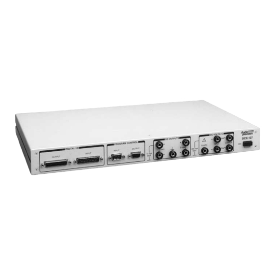
DCX-127
Multifunction Module
User's Guide
NOTICE TO EU CUSTOMERS
This product is not updated to comply with RoHS Directive 2011/65/EU and, as of July 22, 2019, will not
be shipped to the European Union (EU). Customers may be able to purchase products from inventory
that were placed on the EU market prior to July 22, 2019 until supplies are depleted. Audio Precision is
committed to assisting with your audio measurement needs. Please contact your local AP sales
representative for further assistance or to determine if alternative product(s) are available.
June 2000
Audio Precision PN 8211.0122
Version 1
Advertisement
Table of Contents

Related Manuals for Audio Precision DCX-127

Summary of Contents for Audio Precision DCX-127
- Page 1 European Union (EU). Customers may be able to purchase products from inventory that were placed on the EU market prior to July 22, 2019 until supplies are depleted. Audio Precision is committed to assisting with your audio measurement needs. Please contact your local AP sales representative for further assistance or to determine if alternative product(s) are available.
- Page 2 Audio Precision®, System One®, System Two™, System Two Cascade™, System One + DSP™, System Two + DSP™, Dual Domain®, FASTTEST®, and APWIN™ are trademarks of Audio Precision, Inc.
-
Page 3: Table Of Contents
Auxiliary Outputs ....26 Specifications ..... 29 DCX-127 Multifunction Module User’s Guide Page iii... -
Page 4: Safety Information
Safety Information Do NOT service or repair this product unless properly qualified. Only a qualified technician or an authorized Audio Precision distributor should perform servicing. Do NOT defeat the safety ground connection. This product is designed to operate only from a 50/60 Hz AC power source (250 Vrms maximum) with an approved three-conductor power cord and safety grounding. -
Page 5: Safety Symbols
Disclaimer Audio Precision cautions against using their products in a manner not specified by the manufacturer. To do otherwise may void any warranties, damage equipment, or pose a safety risk to personnel. -
Page 6: Description
Description Scope of This Manual This manual serves several purposes: § It will help you install the DCX-127 Multifunction Module. In addition to the instrument capabilities, descriptions of all connectors are given. § It presents specifications of the DCX-127. §... -
Page 7: Dc Voltage Measurements
APWIN software and may be displayed as bargraphs or plotted values during a sweep when appropriate. The DCX-127 Multifunction Module is a separate unit packaged in a one-rack-unit high case that may be rack-mounted or used as a bench instrument. -
Page 8: Resistance Measurements
Software features also permit displaying a computed value which is a function of resistance, using user-entered values of offset and scale parameters. The DCX-127 input configuration permits making these resistance measurements on either a 2-wire or 4-wire basis. - Page 9 -INPUT If only one pair of test leads is used, connected from the (+) and (-) terminals of the DCX-127 to the unknown resistance, a 2-wire measurement results. Current from the internal current source flows through an internal resistor, through the test leads and resistance being measured, and through another internal resistor back to the current source.
-
Page 10: Dc Voltage Outputs
Table 1 on page 3. DC Voltage Outputs Two independent dc voltage outputs are available at the DCX-127 front panel. Each output may be set with 20 microvolt resolution (approximately 20 bits equivalent) to any voltage in the ±10.5000 volt range. -
Page 11: Digital Input
A common application of the digital input is in static (DC) linearity testing of A/D converters. The digital input may also be used to interface readings from a BCD-display instrument such as a capacitance meter to the audio test system. Page 6 DCX-127 Multifunction Module User’s Guide... -
Page 12: Digital Output
A parallel digital word of up to 21 bits plus sign bit, at LSTTL-compatible levels, may be connected to the digital input connector on the front panel of the DCX-127. The value of this word may be displayed in decimal or hexadecimal representations. A user-entered scale factor may be entered and a function of actual input displayed, multiplied by the scale factor. -
Page 13: Program Control Outputs
Table above. All lines are LSTTL compatible. The Reset output, pin 2, pulses high when the DCX-127 power is turned on and whenever a Util Restore menu command is executed. The Reset output would typically be used to normalize the condition of external logic devices connected to a System One or System Two test station at power up. - Page 14 DCX-127 Multifunction Module User’s Guide Page 9...
-
Page 15: Auxiliary Output Ports
Auxiliary Output Ports Description Auxiliary Output Ports Three rear-panel 9-pin connectors are provided on the DCX-127 for digital control of external devices. These output ports are intended for direct interface to LSTTL circuitry, or via LSTTL-compatible drivers to relays. Control of power, lights, and annunciators are among the possible applications. -
Page 16: Installation
Installation Mounting DCX-127 modules may be either rack-mounted or simply stacked with other instruments. They do not consume appreciable power, and therefore require no extraordinary ventilation considerations. The modules occupy one rack unit of height (1.75 inches). They are provided with bottom feet for tabletop use. The optional rack mount... - Page 17 (refer to fuse ratings marked on the rear panel or in the manual). If necessary, change the fuse type as described in the following section. 7. Replace the cover and verify that the indicator pin shows the desired voltage. Page 12 DCX-127 Multifunction Module User’s Guide...
-
Page 18: Fuse Information
120 V inputs, or 100 mA for 230 – 240 V inputs. Confirm this information on the label on rear panel. Jumper bar Fuse block Fuse Cover Figure 6. North American fusing arrangement Fuses Fuse block Jumper bar Cover Figure 7 . European fusing arrangement DCX-127 Multifunction Module User’s Guide Page 13... -
Page 19: Changing Fusing Arrangement
5. Change or add the correct fuses as necessary (again, refer to rear panel for the correct fuse current rating). 6. Confirm the line voltage setting as described in the previous section, then replace the cover. Page 14 DCX-127 Multifunction Module User’s Guide... -
Page 20: Power Switch
Refer to the specifications for temperature range and humidity specifications. Connecting the APIB Interface The DCX-127 has two APIB connectors on its rear panel. They permit connecting instruments in a “daisy-chain” fashion between the computer’s APIB card connector and the System One, System Two, or System Two Cascade APIB connector. -
Page 21: Connecting The Apib Interface
100/120 VAC 100/120 VAC 200mA T/SB 250V 200mA T/SB 250V 230/240 VAC 230/240 VAC 100mA T/SB 250V 100mA T/SB 250V Figure 10. APIB connections block diagram (typical; shown with DCX-127 and two switchers) Page 16 DCX-127 Multifunction Module User’s Guide... -
Page 22: Operation
Figure 11. DCX-127 panel, small version The DCX-127 Panel can be viewed in both large and small versions. Clicking on the panel icon on the Panels Toolbar brings up the small version panel, shown in Figure 11. Holding down the key while clicking on the toolbar icon brings up the large version, shown in Figure 12. -
Page 23: Volts/Ohms Measurements
Panel Operation Figure 12. DCX-127 panel, large version Volts/Ohms Measurements Figure 13. Connectors for volt/ohms measurements Page 18 DCX-127 Multifunction Module User’s Guide... - Page 24 The “measurement” term is the value which would be displayed in volts or ohms units. The “Offset” and “Scale” values are the contents of the fields with those names, at the top right of the DCX-127 panel. New entries may be typed into either field, or the existing entry edited, from the keyboard followed by pressing the key.
- Page 25 To use the Guard, connect its terminal to the DUT’s ground, common point, or to the – terminal of the DCX-127, in that order of preference. The peak voltage applied to the guard should not exceed ±500 V.
-
Page 26: Dc Output 1 And 2 On/Off
Either DC output may be independently set to any voltage in the range ±10.5 Vdc. A new value may be entered or the existing value may be edited from the keyboard, followed by the key. DCX-127 Multifunction Module User’s Guide Page 21... -
Page 27: Digital Input And Output
“measurement” is the decimal value of the binary data in the selected format and “Scale (g)” is the value entered in the Scale (g) field just below the Digital In display. A new Scale value may be Page 22 DCX-127 Multifunction Module User’s Guide... - Page 28 Bit 15 3rd digit, 8 Bit 16 2nd digit, 1 Bit 17 2nd digit, 2 Bit 18 2nd digit, 4 Bit 19 2nd digit, 8 Bit 20 (LSB) MS digit, 1 Sign Sign DCX-127 Multifunction Module User’s Guide Page 23...
- Page 29 Out numeric field and “Scale (h)” is the value entered in the Scale (h) field just below the Digital Out control field. A new Scale value may be entered or the present value edited from the keyboard, followed by pressing the E key. Page 24 DCX-127 Multifunction Module User’s Guide...
-
Page 30: Program Control, Gate Delay
However, the delayed sweep gate does not go low until the Gate Delay time has elapsed after the beginning of a sweep. DCX-127 Multifunction Module User’s Guide Page 25... -
Page 31: Auxiliary Outputs
Bit 5 Trigger Bit 4 Undefined Bit 3 Sweep Gate Bit 2 Channel A/B Bit 1 Ground Bit 0 (LSB) Ground Ground Auxiliary Outputs Figure 17. Connectors for Auxiliary Outputs, showing pin numbering Page 26 DCX-127 Multifunction Module User’s Guide... - Page 32 Ports A, B, and C Auxiliary Output Ports A, B, and C are independent 8-bit digital control ports at separate DB9 connectors on the rear of the DCX-127. The settings of the 8 bits may be controlled from the DCX software panel or they may be swept over a range via the Sweep Panel.
- Page 33 J141 J141 Number Number Ground Bit 0 (LSB) Bit 7 (MSB) +5 V Bit 6 +5 V Bit 5 +15 V Bit 4 -15 V Bit 3 Ground Bit 2 Ground Bit 1 Page 28 DCX-127 Multifunction Module User’s Guide...
-
Page 34: Specifications
Valid from + 15°C to +30°C, <80% RH, for 1 year. Derate linearly to Valid from + 15°C to +30°C, <80% RH, for 1 year. Derate linearly to 2 times indicated values at + 5°C and +40°C. 2 times indicated values at + 5°C and +40°C. DCX-127 Multifunction Module User’s Guide Page 29... - Page 35 Full scale on the 2 MW range is 2.50 MW. Load current must be £ 1 mA for specified accuracy. Output resistance is Load current must be £ 1 mA for specified accuracy. Output resistance is typically <0.1 W. typically <0.1 W. Page 30 DCX-127 Multifunction Module User’s Guide...
- Page 36 22-bit (21 bits data + sign) words, plus data Configuration valid/new data strobes. 25-pin D-subminiature connectors. Approximately 8 msec/transfer, limited by computer Maximum data rate speed AUXILIARY OUTPUT PORTS Three independent 8-bit parallel output ports. 9-pin Configuration female D subminiature connectors DCX-127 Multifunction Module User’s Guide Page 31...
- Page 37 0 – 5V. Output drive +5mA/bit maximum. Dimensions 17 in. Wide, 1.75 in. High, 10.5 in. deep Operating + 5°C to +40°C, <80% relative humidity temperature 100/120/220/240 Vac + 5/-10%); 48-63 Hz; 20 VA Power requirements maximum Page 32 DCX-127 Multifunction Module User’s Guide...
Need help?
Do you have a question about the DCX-127 and is the answer not in the manual?
Questions and answers