
Summary of Contents for Gopel Electronic basicCON 4121 Video Dragon
- Page 1 basicCON 4121 Video Dragon User Manual (Translation of Original docu) Document Version 1.7 GOEPEL electronic GmbH Goeschwitzer Str. 58/60 •D-07745 Jena + 49-3641-6896-597 • ats_support@goepel.com • www.goepel.com...
- Page 2 © 2022 GOEPEL electronic GmbH. All rights reserved. The software described in this manual as well as the manual itself are supplied under license and may be used or copied only in accordance with the terms of the license. The customer may make one copy of the software for safety purposes. The contents of the manual is subject to change without prior notice and is supplied for information only.
-
Page 3: Table Of Contents
ble of Contents INSTALLATION AND WARRANTY ........1-1 ............1-1 COPE OF ELIVERY ........... 1-1 ARDWARE NSTALLATION 1.2.1 Connect the Video Dragon ........1-1 1.2.2 Module Change ............1-2 ............1-3 RIVER NSTALLATION 1.3.1 USB ............... 1-3 1.3.2 Ethernet..............1-5 .............. - Page 4 Table of Contents VIDEO DRAGON – FIRST STEPS ........3-1 ........... 3-1 SSEMBLY OF THE YSTEM ............3-2 EVICE EGISTRATION ............... 3-3 ONFIGURATION ..............3-5 APTURING basicCON 4121 – User Manual...
-
Page 5: Installation And Warranty
Installation and Warranty Installation and Warranty Scope of Delivery The following parts belong to a delivery of your GOEPEL electronic Video Dragon basicCON 4121: 1x Video Dragon basic device 1x Media Interface Module (according to your order, already installed) Power supply Unit ... -
Page 6: Module Change
Installation and Warranty 1.2.2 Module Media Interface Modules enable your Video Dragon to perform a Change multitude of different Test tasks; and they are compatible to diverse systems. Therefore it can be required to install a new Media Interface Module for a new Test task. Please make absolutely certain that all of the hardware installation procedures described below are carried out with your system switched off. -
Page 7: River Nstallation
Installation and Warranty Driver Installation 1.3.1 To install the GOEPEL electronic USB drivers on your system, execute the G-USB driver setup. G-USB-Setup-*.exe For this, start the setup program (the asterisk stands for the version number) of the delivered CD, and follow the instructions. - Page 8 Installation and Warranty ® After the installation, you can check by the Windows Device Manager whether the unit is properly embedded by the system. As an example, the following figure shows the successful embedding of one basicCON 4121 device: Figure 1-2: An installed basicCON 4121 in the Windows ®...
-
Page 9: Ethernet
Installation and Warranty 1.3.2 Ethernet If the Ethernet interface is used for communication with the control PC or laptop, there is no driver installation required. Nevertheless, to address the Video Dragon basicCON 4121, you need a network device that is set up with a valid IP Address and proper subnet mask. - Page 10 Installation and Warranty If the network device has been set up right, after the Hardware Installation, the Video Dragon can directly be addressed via the IP Address (see also Addressing). This IP Address can be changed by the HardwareExplorer. The newly set IP Address becomes effective after a restart of your Video Dragon.
-
Page 11: Warranty
Installation and Warranty Warranty Warranty Conditions GOEPEL electronic GmbH guarantees the Test system’s faultlessness for 24 months, beginning with its delivery. Warranty is NOT granted for faults resulting from inappropriate use, modifications or unintended use. Designation of Warranty cases We may ask you to designate cases of warranty clearly. Repairing orders without the notification of a warranty claim are initially executed with costs. -
Page 13: Video Dragon Hardware
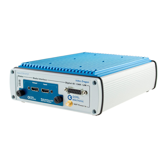
Hardware Video Dragon Hardware General Characteristics Video Dragon basicCON 4121 is a GOEPEL electronic GmbH test system with USB 3.0 and Gigabit Ethernet Interface to transmit or receive video data. The test system has been especially adapted to the requirements and transmission standards of the automotive industry. This way, in addition to the video data, also audio data and control data can be handled. - Page 14 Hardware Video Dragon basicCON 4121 is a stand-alone device to be connected to a PC or laptop. It was developed for applications out of complex test systems. Figure 2-1: Video Dragon – Front view Figure 2-2: Video Dragon – Rear view basicCON 4121 –...
-
Page 15: Technical Data
Hardware Technical Data 2.2.1 Dimensions (Length x Width x Height): 203mm x 172mm x 66mm (without Media Interface Module) 216mm x 172mm x 66mm (with Media Interface Module) 2.2.2 Electrical The following table shows the electrical characteristics of the device- Characteristics specific interfaces (without mentioning the standardized interfaces like HDMI, Ethernet, USB, eSATA and S/PDIF as well as the interfaces... -
Page 16: Mainboard
Hardware Mainboard 2.3.1 Structure By its open hardware concept (see Figure 2-3), the GOEPEL electronic Video Dragon basicCON 4121 with its changeable Media Interface Module and the following FPGA is optimally prepared for executing a multitude of current and future test tasks. Video Dragon consists of a mainboard in a passively cooled box and a changeable Media Interface Module supporting the different transmission standards. -
Page 17: Connections
Hardware 2.3.2 Connections The following two figures show all connections of the Video Dragon: Figure 2-4: Connections – Rear side Power Power supply input (7 to 28V DC) IP Reset Reset button for resetting the IP address Gigabit Ethernet connector for connection to the control PC USB connector for connection to the control PC S/PDIF Out S/PDIF output for audio recording with external devices... -
Page 18: Power Supply
Hardware On the front side, you find the following elements: Figure 2-5: Connections – Front side (8) UUT Power In UUT Supply – depending on the Media Interface Module (9) Digital IO/ CAN 15-pole DSUB socket for connecting the digital I/Os as well as the integrated CAN bus (10) Media Interface Media Interface Module included in the Media Interface Slot... -
Page 19: Addressing
Hardware 2.3.5 Addressing The Video Dragon has an Ethernet and a USB interface, alternatively used for the control. Addressing for several connected devices is effected as follows: In the case the Ethernet interface (3) is used, the device can be addressed by the Default IP Address 192.168.1.62, Port 5134 (see chapter Ethernet). -
Page 20: Esata
Hardware 2.3.9 eSATA By means of the Video Dragon, input data can be recorded, and output data can be buffered on an externally connected hard disk. Thereby, the Video Dragon can be operated without a control PC. Hard disks of SATA I/II/III types can be connected. But best performance results when connecting a SATA II type hard disk, as the interface is designed for that. -
Page 21: Uut Supply
Hardware 2.3.11 UUT Supply The UUT Power In UUT supply connector (8) is used for UUT supply via the connectors of the Media Interface Module. This connector is an SMA socket, having the Plus (+) contact inside and the Ground outside. -
Page 22: Digital Io/ Can
Hardware 2.3.12 Digital IO/ The Digital IO/ CAN connector (9) includes all signals independent of the Media Interface Module for communication and interaction with the test object. With this, universal digital inputs and outputs are available for the user, as well as optionally one CAN port. Find the Electrical Characteristics of the interfaces in the... - Page 23 Hardware For CAN, a plug-in transceiver board is used. This transceiver board is an optional accessory and can be installed also subsequently. For this, the Media Interface Module has to be removed (see Module Change), and the board must be plugged to its plug-in position (see the following Figure): Figure 2-8: Position of Transceiver...
-
Page 24: Galvanic Isolation
Hardware 2.3.13 Galvanic Electric surges can harm expensive test equipment and lead to Isolation unreliable test results. Electric isolation protects against electric surges and can help to suppress dangerous electrical transients. It also eliminates ground loops, responsible for data errors due to ground potential differences. - Page 25 Hardware In the following table, the pin assignment (example) of the INAP375T in the test object (UUT) is confronted with the pin assignment of the INAP375R in the Video Dragon: INAP375T in the UUT INAP375R in the Video Dragon Pin Name Connected Signal Pin Name Connected Signal...
- Page 26 Hardware For this example, the routing table of the Video Dragon would look like this: Pin-Name Signal Connected Vertical Synchron Video Bit 3 Horizontal Synchron Video Bit 2 Data Enable Video Bit 4 disabled disabled Video Bit 5 Video Bit 6 Video Bit 7 Video Bit 8 Video Bit 9...
-
Page 27: Media Interface Modules
Hardware Media Interface Modules 2.4.1 Overview The Media Interface Module cares for the adaption of the Video Dragon basicCON4121 to the respective test object. By the multitude of transmission standards to exchange multimedia data used in the automotive industry, a universal link is not possible otherwise. A transmission system always consists of a transmitter and a receiver suitable for that. - Page 28 Hardware In the following table, the currently available Generator modules and the supporting Standards are listed: Module Name Transmission Compatible Receiver ICs (Serializer) Standard (Deserializers) INAP375T APIX 2 INAP375R, INAP378R APIX 1 INAP125R INAP375T MII APIX 2 INAP375R, INAP378R DS90UB926, DS90UH926*), DS90UB947 FPD-Link III DS90UB928, DS90UH928*),...
- Page 29 Hardware In the following table, the currently available Grabber modules and the supporting Standards are listed: Module Name Transmission Compatible Transmitter ICs (Deserializers) Standard (Serializers) INAP375R APIX 2 INAP375T, INAP378T APIX 1 INAP125T INAP375R MII APIX 2 INAP375T, INAP378T DS90UB925, DS90UH925*), DS90UB948 FPD-Link III DS90UB927, DS90UH927*),...
- Page 30 Hardware As you can see in the tables, most modules support several standards, as they often have a mode for backward compatibility to previous systems. The modules have different connectors, more detailed described in the chapters regarding the corresponding module. As a rule, a Generator module has only one connector, used as video output.
-
Page 31: Inap375T
Hardware 2.4.2 INAP375T The INAP375T interface module is a Generator module supporting the APIX 2 standard (Automotive Pixel Link). It includes the INAP375T transmitter of Inova Semiconductors. The module has the following characteristics: Backward compatible to APIX 1 Downstream link with 3GBits/s band width ... - Page 32 Hardware The pin assignment of the Video signals on the interface module, required for the Video signal routing (see chapter Video signal Routing), is as follows: Pin-Name Connected signal Video PXCLK Video Bit 2 Video Bit 3 Video Bit 4 Video Bit 5 Video Bit 6 Video Bit 7...
-
Page 33: Inap375R
Hardware 2.4.3 INAP375R The INAP375R interface module is a Grabber module supporting the APIX 2 standard (Automotive Pixel Link). It includes the INAP375R receiver of Inova Semiconductors and an INAP375T transmitter for routing through. The module has a second connection and appropriate circuitry, enabling not only signal receiving, but also routing through. - Page 34 Hardware The pin assignment of the Video signals on the interface module, required for the Video signal routing (see chapter Video signal Routing), is as follows: Pin-Name Connected signal Video PXCLK Video Bit 2 Video Bit 3 Video Bit 4 Video Bit 5 Video Bit 6 Video Bit 7...
-
Page 35: Inap375T Mii
Hardware 2.4.4 INAP375T MII The INAP375T MII interface module is a Generator module supporting the APIX 2 standard (Automotive Pixel Link). It includes the INAP375T transmitter of Inova Semiconductors. Via an Ethernet Switch, the MII side band of APIX is coupled in or out. The module has the following characteristics: Downstream link with 3GBits/s band width ... - Page 36 Hardware The pin assignment of the Video signals on the interface module, required for the Video signal routing (see chapter Video signal Routing), is as follows: Pin-Name Connected signal Video PXCLK Video Bit 2 Video Bit 3 Video Bit 4 Video Bit 5 Video Bit 6 Video Bit 7...
-
Page 37: Inap375R Mii
Hardware 2.4.5 INAP375R MII The INAP375R MII interface module is a Grabber module supporting the APIX 2 standard (Automotive Pixel Link). It includes the INAP375R receiver of Inova Semiconductors and an INAP375T transmitter for routing through. Via an Ethernet Switch, the MII side band of APIX is coupled in or out. The module has a second connection and appropriate circuitry, enabling not only signal receiving, but also routing through. - Page 38 Hardware The following table shows the assignment of the „ETH over APIX“ connector: Signal Annotation TX1+ Pos. TX Signal of ETH Port1 TX1- Neg. TX Signal of ETH Port1 RX1+ Pos. RX Signal of ETH Port1 TX2- Neg. TX Signal of ETH Port2 TX2+ Pos.
- Page 39 Hardware The pin assignment of the Video signals on the interface module, required for the Video signal routing (see chapter Video signal Routing), is as follows: Pin-Name Connected signal Video PXCLK Video Bit 2 Video Bit 3 Video Bit 4 Video Bit 5 Video Bit 6 Video Bit 7...
-
Page 40: Ds90Ub947
Hardware 2.4.6 DS90UB947 The DS90UB947 interface module is a Generator module supporting the FPD-Link III standard (Flat Panel Display Link). It includes the DS90UB947Q transmitter of Texas Instruments. The module has the following characteristics: 1-lane or 2-lane FPD-Link III interface ... - Page 41 Hardware The pin assignment of the Video signals on the interface module, required for the Video signal routing (see chapter Video signal Routing), is as follows: Pin-Name Connected signal Video PXCLK PCLK R0/ DIN0 Video Bit 0 R1/ DIN1 Video Bit 1 R2/ DIN2 Video Bit 2 R3/ DIN3...
-
Page 42: Ds90Ub948
Hardware 2.4.7 DS90UB948 The DS90UB948 interface module is a Grabber module supporting the FPD-Link III standard (Flat Panel Display Link). It includes the DS90UB948Q receiver of Texas Instruments. The module has a second connection and appropriate circuitry, enabling not only signal receiving, but also routing through. By this, the Grabber module can be inserted into an existing system of transmitter and receiver without changing the system itself. - Page 43 Hardware The pin assignment of the Video signals on the interface module, required for the Video signal routing (see chapter Video signal Routing), is as follows: Pin-Name Connected signal Video PXCLK PCLK R0/ ROUT0 Video Bit 0 R1/ ROUT1 Video Bit 1 R2/ ROUT2 Video Bit 2 R3/ ROUT3...
-
Page 44: Ds90Ub925
Hardware 2.4.8 DS90UB925 The DS90UB925 interface module is a Generator module supporting the FPD-Link III standard (Flat Panel Display Link. It includes the DS90UB925Q transmitter of Texas Instruments. The module has the following characteristics: Backward compatible to FPD-Link II HD Video resolution and Pixel clock frequency up to 85 MHz ... - Page 45 Hardware The pin assignment of the Video signals on the interface module, required for the Video signal routing (see chapter Video signal Routing), is as follows: Pin-Name Connected signal Video PXCLK PCLK R0/ DIN0 Video Bit 0 R1/ DIN1 Video Bit 1 R2/ DIN2 Video Bit 2 R3/ DIN3...
-
Page 46: Ds90Ub926
Hardware 2.4.9 DS90UB926 The DS90UB926 interface module is a Grabber module supporting the FPD-Link III Standard (Flat Panel Display Link). It includes the DS90UB926Q receiver of Texas Instruments and a DS90UB925Q transmitter for routing through in the (DS90UB926+) extended version. The module is available as simple version (DS90UB926) without I2C support as well as extended version (DS90UB926+) with I2C support and UUT supply. - Page 47 Hardware The following table shows the assignment of the “Output” connector for the simple version: Signal Annotation SD_OUT_N Serial data output negative Through_In_Out Routed through from “Input” to “Output” SD_OUT_P Serial data output positive Ground Ground The following table shows the assignment of the “Output” connector for the extended + version: Signal Annotation...
- Page 48 Hardware The pin assignment of the Video signals on the interface module, required for the Video signal routing (see chapter Video signal Routing), is as follows: Pin-Name Connected signal Video PXCLK PCLK R0/ ROUT0 Video Bit 0 R1/ ROUT1 Video Bit 1 R2/ ROUT2 Video Bit 2 R3/ ROUT3...
-
Page 49: Ds90Ub913A
Hardware 2.4.10 DS90UB913A The DS90UB913A interface module is a Generator module supporting the FPD-Link III standard (Flat Panel Display Link). It includes the DS90UB913A transmitter of Texas Instruments. The module has the following characteristics: Pixel clock frequency up to 100 MHz at 10 bits Color depth ... - Page 50 Hardware The pin assignment of the Video signals on the interface module, required for the Video signal routing (see chapter Video signal Routing), is as follows: Pin-Name signal Connected Video PXCLK PCLK DIN0 Video Bit 0 DIN1 Video Bit 1 DIN2 Video Bit 2 DIN3...
-
Page 51: Ds90Ub914A
Hardware 2.4.11 DS90UB914A The DS90UB914A interface module is a Grabber module supporting the FPD-Link III standard (Flat Panel Display Link). It includes the DS90UB14A receiver of Texas Instruments and a DS90UB913A transmitter for routing through. The module has a second connection and appropriate circuitry, enabling not only signal receiving, but also routing through. - Page 52 Hardware The pin assignment of the Video signals on the interface module, required for the Video signal routing (see chapter Video signal Routing), is as follows: Pin-Name signal Connected PCLK Video PXCLK DIN0 Video Bit 0 DIN1 Video Bit 1 DIN2 Video Bit 2 DIN3...
-
Page 53: Ds90Ub905
Hardware 2.4.12 DS90UB905 The DS90UB905 interface module is a generator module supporting the FPD-Link II (Flat Panel Display Link) standard. It includes the DS90UB905Q transmitter of Texas Instruments. The module has the following characteristics: Backward compatible to FPD-Link II 24 bits Color depth ... - Page 54 Hardware The pin assignment of the Video signals on the interface module, required for the Video signal routing (see chapter Video signal Routing), is as follows: Pin-Name signal Connected Video PXCLK PCLK Video Bit 0 Video Bit 1 Video Bit 2 Video Bit 3 Video Bit 4 Video Bit 5...
-
Page 55: Ds90Ur906
Hardware 2.4.13 DS90UR906 The DS90UR906 interface module is a Grabber module supporting the FPD-Link II standard (Flat Panel Display Link). It includes the DS90UBR906Q receiver of Texas Instruments. The module has a second connection and appropriate circuitry, enabling not only signal receiving, but also routing through. By this, the Grabber module can be inserted into an existing system of transmitter and receiver without changing the system itself. - Page 56 Hardware The pin assignment of the Video signals on the interface module, required for the Video signal routing (see chapter Video signal Routing), is as follows: Pin-Name signal Connected Video PXCLK PCLK Video Bit 0 Video Bit 1 Video Bit 2 Video Bit 3 Video Bit 4 Video Bit 5...
-
Page 57: Max9275
Hardware 2.4.14 MAX9275 The MAX9275 interface module is a Generator module supporting the GMSL standard (Gigabit Multimedia Serial Link). It includes the MAX9275 transmitter of Maxim Integrated. The module has the following characteristics: 3.12 GBits/s GMSL 24 bits or 32 bits transmission (colors and control signals) ... - Page 58 Hardware The pin assignment of the Video signals on the interface module, required for the Video signal routing (see chapter Video signal Routing), is as follows: Pin-Name signal Connected Video PXCLK PCLKIN DIN0 Video Bit 0 DIN1 Video Bit 1 DIN2 Video Bit 2 DIN3...
-
Page 59: Max9276
Hardware 2.4.15 MAX9276 The MAX9276 interface module is a Grabber module supporting the GMSL standard (Gigabit Multimedia Serial Link). It includes the MAX9276 receiver of Maxim Integrated and a MAX9275 transmitter for routing through. The module has a second connection and appropriate circuitry, enabling not only signal receiving, but also routing through. - Page 60 Hardware The pin assignment of the Video signals on the interface module, required for the Video signal routing (see chapter Video signal Routing), is as follows: Pin-Name ignal Connected s Video PXCLK DOUT0 Video Bit 0 DOUT1 Video Bit 1 DOUT2 Video Bit 2 DOUT3...
-
Page 61: Max9271
Hardware 2.4.16 MAX9271 The MAX9271 interface module is a Generator module supporting the GMSL standard (Gigabit Multimedia Serial Link). It includes the MAX9271 transmitter of Maxim Integrated. The module has the following characteristics: 1.5 GBits/s GMSL 28 bits transmission (colors and control signals) ... - Page 62 Hardware The pin assignment of the Video signals on the interface module, required for the Video signal routing (see chapter Video signal Routing), is as follows: Pin-Name Connected signal Video PXCLK PCLKIN DIN0 Video Bit 0 DIN1 Video Bit 1 DIN2 Video Bit 2 DIN3...
-
Page 63: Max9272
Hardware 2.4.17 MAX9272 The MAX9272 interface module is a Grabber module supporting the GMSL (Gigabit Multimedia Serial Link) standard. It includes a MAX9272 receiver of Maxim Integrated and a MAX9273 transmitter for routing through. The Module has a second connection and appropriate circuitry, enabling not only signal receiving, but also routing through. - Page 64 Hardware The pin assignment of the Video signals on the interface module, required for the Video signal routing (see chapter Video signal Routing), is as follows: Pin-Name Connected Signal Video PXCLK PCLKOUT DOUT0 Video Bit 0 DOUT1 Video Bit 1 DOUT2 Video Bit 2 DOUT3...
-
Page 65: Max9259
Hardware 2.4.18 MAX9259 The MAX9259 interface module is a Generator module supporting the GMSL standard (Gigabit Multimedia Serial Link). It includes the MAX9259 transmitter of Maxim Integrated. The module has the following characteristics: 24 bits or 32 bits transmission (colors and control signals) ... - Page 66 Hardware The pin assignment of the Video signals on the interface module, required for the Video signal routing (see chapter Video signal Routing), is as follows: Pin-Name signal Connected Video PXCLK PCLKIN DIN0 Video Bit 0 DIN1 Video Bit 1 DIN2 Video Bit 2 DIN3...
-
Page 67: Max9260
Hardware 2.4.19 MAX9260 The MAX9260 interface module is a Grabber module supporting the GMSL standard (Gigabit Multimedia Serial Link). It includes the MAX9260 receiver of Maxim Integrated and a MAX9259 transmitter for routing through. The module has a second connection and appropriate circuitry, enabling not only signal receiving, but also routing through. - Page 68 Hardware The pin assignment of the Video signals on the interface module, required for the Video signal routing (see chapter Video signal Routing), is as follows: Pin-Name signal Connected Video PXCLK PCLKOUT DOUT0 Video Bit 0 DOUT1 Video Bit 1 DOUT2 Video Bit 2 DOUT3...
-
Page 69: Max9247
Hardware 2.4.20 MAX9247 The MAX9247 interface module is a Generator module including the MAX9247 transmitter of Maxim Integrated. The module has the following characteristics: 18 bits Color depth Pixel clock frequency up to 42 MHz 9 bits for control signals ... - Page 70 Hardware The pin assignment of the Video signals on the interface module, required for the Video signal routing (see chapter Video signal Routing), is as follows: Pin-Name signal Connected Video PXCLK PCLK_IN RGB_IN0 Video Bit 0 RGB_IN1 Video Bit 1 RGB_IN2 Video Bit 2 RGB_IN3...
-
Page 71: Max9248
Hardware 2.4.21 MAX9248 The MAX9248 interface module is a Grabber module including the MAX9248 receiver of Maxim Integrated. The module has a second connection and appropriate circuitry, enabling not only signal receiving, but also routing through. By this, the Grabber module can be inserted into an existing system of transmitter and receiver without changing the system itself. - Page 72 Hardware The pin assignment of the Video signals on the interface module, required for the Video signal routing (see chapter Video signal Routing), is as follows: Pin-Name signal Connected Video PXCLK PCLK_OUT RGB_OUT0 Video Bit 0 RGB_OUT1 Video Bit 1 RGB_OUT2 Video Bit 2 RGB_OUT3...
-
Page 73: Adv7611
Hardware 2.4.22 ADV7611 The ADV7611 interface module is a Grabber module supporting the HDMI 1.3a standard. It includes the ADV7611 receiver of Analog Devices. The module has a second connection and appropriate circuitry, enabling not only signal receiving, but also routing through. By this, the Grabber module can be inserted into an existing system of transmitter and receiver without changing the system itself. - Page 74 Hardware The pin assignment of the Video signals on the interface module, required for the Video signal routing (see chapter Video signal Routing), is as follows: Pin Name Connected signal Video PXCLK Video Bit 0 Video Bit 1 Video Bit 2 Video Bit 3 Video Bit 4 Video Bit 5...
-
Page 75: Rgb888T
Hardware The RGB888T Interface Module is a Generator module for video 2.4.23 RGB888T frames in RGB888 format. The module has the following characteristics: 24 bits Color depth Pixel clock frequency up to 33 MHz 4 bits for control signals ... - Page 76 Hardware Signal Annotation Video Bit 22 Video Bit 23 Ground Video PXCLK Video Pixelclock Ground Video Bit 24 Video Bit 26 Video Bit 25 Not Connected Not Connected Not Connected Not Connected Ground Not Connected Not Connected Not Connected Not Connected Not Connected Not Connected 2-64...
-
Page 77: Rgb888R
Hardware 2.4.24 RGB888R The RGB888R Interface Module is a Grabber module for video frames in RGB888 format. The module has the following characteristics: 24 bits Color depth Pixel clock frequency up to 33 MHz 4 bits for control signals ... - Page 78 Hardware Signal Annotation Video Bit 22 Video Bit 23 Ground Video PXCLK Video Pixelclock Ground Video Bit 24 Video Bit 26 Video Bit 25 Not Connected Not Connected Not Connected Not Connected Ground Not Connected Not Connected Not Connected Not Connected Not Connected Not Connected 2-66...
-
Page 79: Video Dragon - First Steps
First Steps Video Dragon – First Steps Requirement for these steps is a proper installation of the GOEPEL electronic G-API and the LvdsViewer software (see separate manuals). The Video Dragon basicCON 4121 can be used with different Media Interface Modules (see the Media Interface Modules chapter). -
Page 80: Device Registration
First Steps Device Registration Before using the GOEPEL electronic Video Dragon basicCON 4121 for the very first time, the device must be registered at the G-API, which is responsible for all further communication between the control PC or laptop and the device. This registration is simply done by starting the HardwareExplorer. -
Page 81: Configuration
First Steps Configuration Before the capturing of frames is possible, the basicCON 4121 needs to be configured, according to the actually transmitted Video signal. 1. Start the GOEPEL electronic LvdsViewer software. 2. Select the LVDS interface of the basicCON 4121 by its name seen in the HardwareExplorer (“LVDS1”... - Page 82 First Steps 7. Click “OK” to close the settings dialog. Optionally you can click the “Save” button before, to save the settings for the selected LVDS interface permanently. 8. Click the LVDS info button ( ) in the main window. A window with information about the current hardware and software version of the basicCON 4121 as well as about the Video signal appears:...
-
Page 83: Capturing
First Steps Capturing It is possible to capture either single frames or a sequence of frames. By clicking the “Capture single frame” button ( ) a single frame from the video stream will be captured and displayed in the frame area of the LvdsViewer. - Page 85 Index MAX9259 ..... 2-53 MAX9271 ..... 2-49 MAX9275 ..... 2-45 RGB888T ..... 2-63 Addressing ......2-7 Grabber-Modules Ethernet ......2-7 ADV7611 ..... 2-61 USB ......2-7 DS90UB914A ....2-39 ADV7611 ......2-61 DS90UB926 ....2-34 DS90UB948 ....2-30 DS90UR906 ....2-43 INAP375R ....
- Page 86 Index Block diagram ....2-4 Connections....2-5 Driver Installation ..1-3 S/PDIF connection ..... 2-7 Electrical characteristics .. 2-3 Scope of Delivery ....1-1 Ethernet ......1-5 Status LEDs ...... 2-6 Front/ Rear view .... 2-2 Structure ......2-4 General notes ....2-1 Performance characteristics .........
Need help?
Do you have a question about the basicCON 4121 Video Dragon and is the answer not in the manual?
Questions and answers