Table of Contents
Advertisement
PURE SINE WAVE INVERTER
USER MANUAL
PS1001-NP
PS1003-NP
PS1005-NP
IMPORTANT SAFETY INFORMATION. SAVE THESE INSTRUCTIONS.
TO REDUCE THE RISK OF INJURY, USER MUST READ AND UNDERSTAND THIS INSTRUCTIONAL
MANUAL. THIS MANUAL CONTAINS IMPORTANT INFORMATION REGARDING THE OPERATION
AND INSTALLATION OF PRODUCT. PLEASE RETAIN FOR FUTURE REFERENCE.
WWW.GOWISEPOWER.COM
PS1002-NP
PS1004-NP
PS1006-NP
Advertisement
Table of Contents

Related Manuals for GoWISE PS1001-NP


Summary of Contents for GoWISE PS1001-NP
- Page 1 PURE SINE WAVE INVERTER USER MANUAL PS1001-NP PS1002-NP PS1003-NP PS1004-NP PS1005-NP PS1006-NP IMPORTANT SAFETY INFORMATION. SAVE THESE INSTRUCTIONS. TO REDUCE THE RISK OF INJURY, USER MUST READ AND UNDERSTAND THIS INSTRUCTIONAL MANUAL. THIS MANUAL CONTAINS IMPORTANT INFORMATION REGARDING THE OPERATION AND INSTALLATION OF PRODUCT.
-
Page 2: Unpacking & Inspection
THANK YOU FOR YOUR PURCHASE! UNPACKING & INSPECTION Thoroughly inspect the products. The package should contain the following: Inverter 1. 1. 2 Ft. + (Red) and - (Black) DC Cable 2. 2. Remote 3. 3. 15 Ft. Cable 4. 4. User Manual 5. -
Page 3: Table Of Contents
TABLE OF CONTENTS Unpacking & Inspection......Introduction..........Standard Features......Protection Features....... Remote......... Safety Instructions......... General Safety Instructions.... Battery Precautions....... DC Connection Precautions ..Personal Safety Precautions ..General Overview........Display Overview......Installation..........Preparing for Installation....Inverter Unit Location..... Installation Guide......Installation Materials...... -
Page 4: Introduction
INTRODUCTION GoWISE Power Pure Sine Wave Inverters provide the convenience of household type power to run a wide variety of appliances, with low THD <3%. GoWISE Power Inverters converts 12.5 VDC to 115 VAC household power. • This unit uses the latest in soft start technology. The output voltage gradually increases to the normal value from low value after the inverter is turned on. -
Page 5: Protection Features
INTRODUCTION GoWISE Power Pure Sine Wave Inverters are protected by a variety of features including: Reverse Polarity Protection The fuses will burn out when the positive and negative cables are reverse connected to protect the inverter. Low Battery Shutdown When the inverter is in low voltage, an alarm will go off first and if the voltage continues to reduce, the LED will turn red and the inverter will shut down. -
Page 6: Remote
INTRODUCTION GoWISE Power Pure Sine Wave Inverter Remote 1. 1. The Inverter Includes a remote, mounting screws, and 15 Ft. cable. 2. 2. The remote is designed to be mounted on a dash or other flat surface. 3. 3. The remote cable should be plugged into inverter and the remote before being mounted. -
Page 7: Safety Instructions
CAUTION! • DO NOT expose this unit to rain or snow. • Use of attachments not recommended or sold by GoWISE Power will void warranty and may result in the risk of fire, electrical shock or personal injury. • To reduce the risk of electrical shock, remove connection to AC power and DC connections prior to maintenance or cleaning. -
Page 8: Battery Precautions
SAFETY INSTRUCTIONS BATTERY PRECAUTIONS To reduce risk of battery explosion, follow these instructions and those published by battery manufacturer and manufacturer of any unit you intend to use in vicinity of battery. Review cautionary marking on these products and on engine. - Page 9 SAFETY INSTRUCTIONS PERSONAL SAFETY PRECAUTIONS (cont.) WARNING: Restrictions on Use - The Power Inverter shall not be used in connection with life support systems or other medical equipment devices. DANGER • HIGH VOLTAGE AVOID SERIOUS INJURY OR DEATH FROM ELECTRICAL SHOCK. BEFORE PERFORMING ANY ELECTRICAL WORK TURN OFF AC POWER SUPPLY.
-
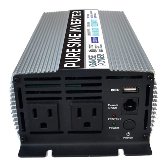
Page 10: General Overview
GENERAL OVERVIEW PS1 001-NP COOLING FAN GROUND LUG TERMINAL REMOTE AC OUTLETS ON/OFF SWITCH POWER INPUT TERMINAL POWER INPUT TERMINAL (RED) = POSITIVE (BLACK ) = NEGATIVE PS1 002-NP GROUND LUG TERMINAL COOLING FAN AC OUTLETS REMOTE ON/OFF SWITCH POWER INPUT POWER INPUT TERMINAL TERMINAL (RED) (BLACK ) = NEGATIVE... -
Page 11: Display Overview
GENERAL OVERVIEW DISPLAY OVERVIEW Description Details Power Button Turns on/off the inverter Power Indicator Green LED for 12.5V DC Input Protect Indicator Illuminates red when the Off inverter is in fault condition System Status Fault Modes All faults conditions are accompanied by a 2-second alarm (On/Off tone). -
Page 12: Installation
INSTALLATION PREPARING FOR INSTALLATION WARNING • This device is not ignition protected, risk of fire or explosion. • This equipment contains components that could produce arcs or sparks. To reduce the risk of fire or explosion, DO NOT install this equipment in compartments containing batteries, flammable materials or fumes, or in a location containing gasoline-powered machinery, or joints, fittings, or other connections between components of the fuel system. -
Page 13: Inverter Unit Location
INSTALLATION INVERTER UNIT LOCATION NOTE: Please re-read the PERSONAL SAFETY PRECAUTIONS section of this manual (pg. 8-9) prior to installation. This unit must be located in a cool, dry, well ventilated area, free from unsecured hardware. Temperature is also a serious consideration. -
Page 14: Installation Guide
INSTALLATION INSTALLATION GUIDE STOP: BEFORE INSTALLING YOUR INVERTER, READ AND FOLLOW THE CHECKLIST BELOW: • Begin with the power switch and main shore/station power breaker in the OFF position. Ensure that all over current protection (e.g. fuses and/or circuit breakers) are ready for use, not blown or tripped. •... -
Page 15: Installation Materials
Cable Size - Size is based on amperage draw of the unit compared to the maximum amperage a cable can carry. We recommend NO MORE THAN a 10% drop in voltage from source (battery) to the GoWISE Power unit or a cable run not longer than 6 feet. -
Page 16: Operation
OPERATION Inverter Power On and Off The AC output can be turned on or off by pressing the POWER button on the display panel. With the remote feature, the inverter can be turned on or off remotely as well. Operating the Inverter within the Load Range Load Type Precautions •... -
Page 17: Maintenance
MAINTENANCE BATTERY MAINTENANCE Periodically, check the batteries to make sure they are good condition. Check the terminals for corrosion and clean them with a wire brush if necessary. If the batteries are flooded lead-acid, check the electrolyte levels every month and top off with distilled water if needed. -
Page 18: Troubleshooting
TROUBLESHOOTING WARNING ELECTRICAL SHOCK HAZARD DO NOT disassemble the inverter. It does not contain any serviceable parts and attempting to service the unit could result in an electrical shock or burn. Failure to follow these instructions can result in death or serious injury. How to Troubleshoot Common Fault Conditions This section details how to troubleshoot the power inverter. - Page 19 105% SHUTOFF remove if needed and is shutoff • Push button twice to clear fault If the GoWISE Power Pure Sine Wave Inverter still malfunctions after all solutions have been exhausted, please contact our Customer Care Team at 855-233-9199.
-
Page 20: Specifications
SPECIFICATIONS Pure Sine Description 600W 1000W 1500W 2000W 3000W Wave Inverter Input Over-Voltage 15~16.5VDC Protection Input Under- 9.5~10.5VDC Voltage Protection Input Characteristics Voltage Range 11~15VDC No Load Current ≤1A @12.5VDC Continuous Output 600W 1000W 1500W 2000W 3000W Power Surge Power 1200W 2000W 3000W... - Page 21 NOTES...
-
Page 22: Warranty
GoWISE Power warrants all products against defects in materials and workmanship for one (1) year effective from the date of purchase. GoWISE Power will replace any products that are found to be defective due to manufacturer flaws based on eligibility. Refunds issued by GoWISE Power must be purchased directly from GoWISE Power and are only available to the original purchaser within the first 30 days. - Page 23 Serial number, usually found on a sticker located on the bottom 2. 2. on back of the unit Picture or video of the issue or defect that you are experiencing 3. 3. Shipping address information 4. 4. Authorized Retailers: Amazon GoWISE Power...
- Page 24 To ensure the correct use of this unit, read these instructions carefully and thoroughly. www.gowisepower.com • Please keep this manual for future 855-233-9199 reference. support@gowiseusa.com • Thank you for purchasing this Live Chat at gowisepower.com GoWISE Power Pure Sine Wave M-F 8:30am - 4:00pm MST Inverter.
Need help?
Do you have a question about the PS1001-NP and is the answer not in the manual?
Questions and answers
Does the GoWISE-1003 inverter have an integrated transfer switch?