
Summary of Contents for Techcomp Dynamica Velocity 30R
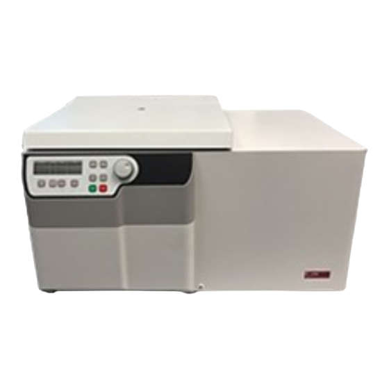
- Page 1 Velocity 30R Benchtop Centrifuge Instruction manual Model VELOCITY 30R High-Speed Refrigerated Benchtop Centrifuge Revision: D01-202006...
-
Page 2: Table Of Contents
CONTENTS 1 PRODUCT DESCRIPTION 1.1 Usage in accordance with safety standards 1.1.1 General Information 1.1.1.1 Hazards and precautions 1.1.1.2 Brief description 1.1.1.3 Safety Standards 1.1.1.4 Extent of supply 1.1.1.5 Warranty 1.2 Installation 1.2.1 Installation of the centrifuge 1.2.1.1 Unpacking the centrifuge 1.2.1.2 Space requirements 1.2.1.3 Installation 1.3 Technical Data... - Page 3 CONTENTS 4 TROUBLESHOOTING 4.1 Error messages: Cause / Solution 4.2 Survey of possible error messages and their solutions 4.2.1 Lid release during power failure 4.2.2 Description of the error message system 4.2.3 Error messages 5 RECEIPT OF CENTRIFUGES TO REPAIR 6 DISPOSAL Page 3 of 36 INSTRUCTION MANUAL VELOCITY 30R...
-
Page 4: Product Description
For your safety, please review the following precautions: • The DYNAMICA VELOCITY 30R is not explosion-proof and therefore must not be operated in explosion-endangered areas or locations. During centrifugation, it is prohibited to stay within the safety zone of 30 cm around the centrifuge or deposit hazardous substances within this area. -
Page 5: Brief Description
1 PRODUCT DESCRIPTION The manufacturer is responsible for the safety and reliability of the centrifuge, only if: • The unit is operated in accordance to this instruction manual. • Modifications, repairs or other adjustments are performed by DYNAMICA-authorized personnel and the electrical installation of the related location corresponds to the IEC-regulations. -
Page 6: Extent Of Supply
1 PRODUCT DESCRIPTION 1.1.1.4 Extent of supply Following parts are supplied as accessories with each centrifuge: • 1 instruction manual • 1 Allen key for removing rotors Spare fuses are at the rear side of the centrifuge. 1.1.1.5 Warranty The centrifuge has been subjected to thorough testing and quality controls. In the case of any manufacturing faults occurring, the centrifuge and rotors are covered by warranty for one year from the date of delivery. -
Page 7: Installation
1 PRODUCT DESCRIPTION 1.2.1.3 Installation Follow these steps: • Check whether power supply corresponds with the one named in the manufacturer's rating label which is mounted on the rear panel. • The line voltage circuit breaker is max. 16 A (type K) slow release for commonly used instruments. •... -
Page 8: Conformity Declaration
1 PRODUCT DESCRIPTION 1.4 Conformity declaration Please refer to the conformity declaration in the package Page 8 of 36 INSTRUCTION MANUAL VELOCITY 30R Dynamica Scientific Limited... -
Page 9: Access To The "Basic Adjustments" Mode
1 PRODUCT DESCRIPTION 1.5 Basic adjustments When putting the centrifuge into operation, you have the options to set up using the following basic adjustments: 1. Temperature indication in °C or °F 2. Sound signal turn on/off 3. Volume pre-selection of a sound signal 4. - Page 10 1 PRODUCT DESCRIPTION 1.5.2 Temperature indication Proceed as described in point 1.5.1 to enter this program mode and then press the key "accel/decel" (12). The word "service" appearsin the display "accel/decel". Now select the letter "C" with the adjusting knob (9). As a result, the word "CELSI/temp"...
- Page 11 1 PRODUCT DESCRIPTION 1.5.4 Volume pre-selection of the sound signal Proceed as described under point 1.5.1 to enter this program mode and then press the key "accel/decel" (12). The word "service" will appear in the display "accel/decel". Now select the letter "U" with the adjusting knob (9). As a result, the words "Vol=/Sound"...
- Page 12 1 PRODUCT DESCRIPTION 1.5.6 Keyboard sound turn on / off Proceed as described under point 1.5.1 to enter this program mode and then press the key "accel/decel" (12). the word "service" will appear in the display "accel/decel". Now select the letter "b" with the adjusting knob (9). As a result, the word "BeeP-x".appears in the display "rpm/rcf"...
- Page 13 1 PRODUCT DESCRIPTION 1.5.7 Call up of operating data you can call up the operating data of the centrifuge in the "Basic Adjustments"mode. Please proceed as described in point 1.5.1 to enter this mode. Press the key "accel/decel" (12). The word "service" will appear in the display "accel/decel". With the adjusting knob (9) the different information can be called up: A = previous start of the centrifuge H = previous operating hours...
-
Page 14: Operation
2 OPERATION 2.1 Installation of rotors 2.1.1 Mounting and loading angle rotors Clean the drive shaft as well as the rotor mounting boring with a clean, grease-free piece of cloth. Place the rotor onto the drive shaft. (see photo 9) Take care that the rotor is fully installed onto the motor shaft. - Page 15 2 OPERATION Hold the rotor with one hand and secure the rotor to the shaft by turning the fixing screw (1) clockwise. Tighten the fixing screw with enclosed Allen key (see photo 11). Photo 11 It is allowed to operate e.g. an 8-place-rotor with 2 or 4 loaded tubes only. But the loaded borings must be opposite to each other.
-
Page 16: Mounting And Loading Swing Out Rotors
2 OPERATION 2.1.2 Mounting and loading swing-out rotors Clean the drive shaft as well as the device hole of the rotor with a clean and grease-free cloth. Put the rotor onto the motor shaft. Take care that the rotor is fully installed onto the motor shaft. Hold the rotor with one hand and secure the rotor to the shaft by turning the rotor nut (1) clockwise. -
Page 17: Overloading Of Rotors
2 OPERATION 2.1.3 Overloading of rotors The maximum load permitted for a rotor, which is determined by the manufacturer, as well as the maximum speed allowed for this rotor (see label on the rotor), must not be exceeded. The liquids the rotors are loaded with, should have an average homogeneous density of 1.2 g/ml or less when the rotor is running at maximum speed. -
Page 18: Power Switch
2 OPERATION 2.2 Operation 2.2.1 Power switch The power switch is located on the bottom, left side of the unit. Thepower switch is also the main fuse of the centrifuge. Attention: After turning on the power switch you must open the lid of the unit first, prior to starting the centrifuge. -
Page 19: Pre-Selection Of Speed/Rcf-Value
2 OPERATION 2.2.4 Pre-selection of speed / RCF-value Through the key "rpm/rcf" (8) this pre-selection is activated. By pressing the key once the word "rpm" (6) flashes. By pressing the key once again the pre-selection of the centrifugal forces may be chosen. Then the flashing word "rcf"... -
Page 20: Pre-Selection Of Running Time
2 OPERATION 2.2.5 Pre-selection of running time The running time can be pre-selected in three different ranges from 10 seconds up to 99 hours 59 minutes. 1. Range from 10 seconds up to 59 minutes 50 seconds in steps of 10 seconds 2. -
Page 21: Pre-Selection Of Brake Intensity And Acceleration
2 OPERATION 2.2.6 Pre-selection of brake intensity and acceleration Through the key "accel/decel" (12) this function is activated. By pressing the key once the word "accel" (13) flashes in the"acc/dec" display. The desired acceleration can be pre-selected by the adjusting knob (9). The value 0 and 9 is equivalent to the lowest the highest acceleration respectively. -
Page 22: Pre-Selection Of Temperature
2 OPERATION 2.2.7 Pre-selection of temperature This function is activated by the key "temp" (15). The indication "°C" (16) flashes and by adjusting knob (9) the desired test temperature can be pre-selected in steps of 1°C in a range from -20°C up to +40°C. The value is indicated permanently in the display (18) - before, during and after the run. -
Page 23: Pre-Cooling
2 OPERATION 2.2.8 Pre-cooling If the samples are temperature-sensitive, it is useful to pre-cool the centrifuge, the rotor and eventually the buckets to the working temperature required. Therefore insert the desired rotor and pre-set the respective temperature. You can start the run by simultaneous pressing "temp" (15) and "time" (10). The unit will automatically choose a rotational speed that is equivalent to 20 % of the permitted rotational speed of the respective rotor during the run. -
Page 24: Storage Of Programs
2 OPERATION 2.2.10 Storage of programs You can store up to 99 runs with all relevant parameters, incl. the rotors used. You can use any free program number and call it up again. Put the needed rotor into the centrifuge. By pressing the key "prog" (21) display the word "programm" (19) appears on the "time"... -
Page 25: Recall Of Stored Programs
2 OPERATION 2.2.11 Recall of stored programs To recall a stored program press "prog" (21) while the lid is closed. The word "programm - - " (19) will appear on the "time" display Using the adjusting knob (9) you can pre-select the desired program number. In the respective displays there will appear the stored values for that program. -
Page 26: Starting The Centrifuge
2 OPERATION 2.2.13 Starting the centrifuge You can start the centrifuge either with the "start" key (23) or the "quick" key (24). With the "start" key (23) you can start a stored run or runs with manually pre-selected parameters. The centrifuge will stop automatically when the respective pre-selected running time has ended. Using the "quick"... -
Page 27: Safety Features
2 OPERATION 2.3 Safety features 2.3.1 Imbalance detection In case of the rotor not being loaded equally, the drive will turn off during acceleration. The rotor will then decelerates until standstill. In the "time" display the word "error" together with the number "01" (26) appear when the weight difference of the samples is too big. -
Page 28: Maintenance
3 MAINTENANCE 3.1 Service and maintenance 3.1.1 Maintenance and cleaning Maintenance: Maintenance of the centrifuge is confined to keeping the rotor, the rotor chamber and the rotor accessories clean as well as lubricating the rotor insert bolts of the swing-out rotor (if available) regularly. -
Page 29: Glass Breakage
3 MAINTENANCE 3.1.2 Glass breakage The rate of glass tube breakage increases with increasing g-values. Glass splinters have to be removed immediately from the rotor, buckets, adapters and the rotor chamber. Fine glass splinters will scratch and therefore damage the protective surface coating of the rotor. If glass splinters remain in the rotor chamber, fine metal dust will build-up due to air circulation. -
Page 30: Troubleshooting
4 TROUBLESHOOTING 4.1 Error messages: cause / solution Preface: The error messages are listed to help identify possible errors faster. The diagnose referred to in this chapter may not always be the case, as they are only theoretically occurring errors and solutions. Always, please keep us informed about any kind of error occurs, which is not listed in this chapter. -
Page 31: Description Of The Error Message System
4 TROUBLESHOOTING 4.2.2 Description of the error message system The error message is shown in the "time" display through particular figures (26). At the same time the word "error" (26) is indicated in the display (see photo 30). Photo 30 4.2.3 Error messages Errors that may be indicated in the LCD: Description... -
Page 32: Receipt Of Centrifuges To Repair
5 RECEIPT OF CENTRIFUGES TO REPAIR Receipt of centrifuges to repair In case of returning the centrifuge to the manufacturer for repairing, please note the following: The centrifuge must be decontaminated and cleaned before shipment for the protection of persons, environment and material. -
Page 33: Disposal
6 DISPOSAL Disposal Please take care that you comply with the respective legal regulations when you dispose of the unit. According to the directive 2002/96/EG (WEEE) all units delivered after the 13.08.2005 must not be disposed of with the domestic waste. This unit belongs to group 8 (Medical Units) and is ranged in the Business-to-Business-Field. - Page 34 Page 34 of 36 INSTRUCTION MANUAL VELOCITY 30R Dynamica Scientific Limited...
- Page 35 Page 35 of 36 INSTRUCTION MANUAL VELOCITY 30R Dynamica Scientific Limited...
- Page 36 The Velocity Range Bench Top Centrifuges Dynamica Scientific Limited 4 Bain Square, Kirkton Campus, Livingston EH54 7DQ, United Kingdom P: +44 1908 211 900 F: +44 1908 211 909 Email: info@dynamica-eu.com Web: www.dynamica-eu.com Asia Dynamica (Asia) Limited Unit 06, 26/F Tower 1, Ever Gain Plaza, 88 Container Port Road, Kwai Chung N.T., Hong Kong P: +852 2751 9488...
Need help?
Do you have a question about the Dynamica Velocity 30R and is the answer not in the manual?
Questions and answers