Table of Contents
Advertisement
Advertisement
Table of Contents

Summary of Contents for Ekotez EkoFlush-K570
-
Page 2: Table Of Contents
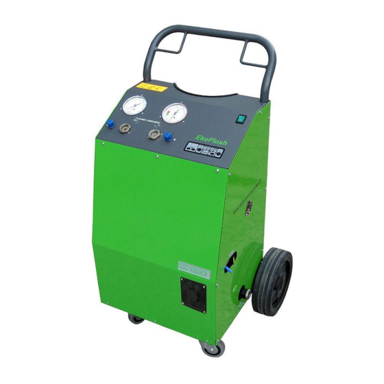
• The EkoFlush-K570 unit can only be transported by transportation means if its refrigerant cylinder is disassembled and transported separately. The main unit can be transported in the standard position on wheels (properly protected against moving), or laid down on its rear side leaning on its handle and wheels. -
Page 3: Unit Description
Unit Description The EkoFlush-K570 is a mobile Flushing unit with wheels and rugged metal structure. A refrigerant cylinder is to be bought with a two-way valve and filled with the flushing agent ® SOLSTICE PF-C from HONEYWELL and pressurized with nitrogen. -
Page 4: Accessories
• ® Flushing agent for systems cleaning SOLSTICE PF-C WARNING ® The Flushing Unit EkoFlush-K570 is designed exclusively for the SOLSTICE PF-C flushing agent made by HONEYWELL. Please see our warning given on page 3, paragraph 3.2. - 4 -... -
Page 5: Main Principles And Interconnection
6. Main principles and interconnection Circuit to be flushed had to be tight and through. Without refrigerant liquid residues (without pressure) If possible, Interconnect the K570 in the circuit instead of compressor. It is necessary to disconnect compressor before flushing procedure. The compressor oil charging would be washed off!! Large circuit has to be flushed in sections, especially circuit with several branches. -
Page 6: Flushing Procedure
7. Device flushing procedure Check the hose interconnection (see capture 6). Open all valves on the refrigerant cylinder and hoses as well. After ending of the complete flushing procedure is the situation identic! After switching on and starting up the unit automatically evacuates the flushed equipment, the next automatically step fills the flushed equipment with the solvent liquid. - Page 7 After dismantling of the upper part (No. 2, 3, 4) withdraw the blocking spring (No.4) and dismantle all single parts (No. 2, 3, 4), which has to be cleaned including the sight glass interior (No. 1). After ending of the flushing it may come (for many reasons) to the pressure loss in the cylinder ®...
-
Page 8: Controlling
Unit controlling – work flow G = green Y = yellow PB = button LED = diode-signal light 8.1. Turn on the main switch. It lights : on display 3times number of remaining flushing procedures. –see 10 8.1.1. Initial status. It lights : on display “1”... - Page 9 8.3. Completing flushing. 8.3.1. By pressing PB 5 – END, if LED 5 blinks and the It shows: on display “1” and LED 1, pressure on the low-pressure manometer (pos. 16) LED 6 is lower than –0,5 bar. (see the note on page 8) Oil and sludge discharge from the distillation chamber 8.4.1 Open the nitrogen supply to the distillation chamber...
-
Page 10: Completing Flushing
7) The maximum capacity of the distillation chamber for oil and residues is about 1 liter. If during the flushing this capacity is filled with contaminants, LED7 (Distillation Chamber Full) will not switch off and the process can “freeze”. It is necessary to discharge the distillation chamber, but first it´s necessary to add pressure to chamber, so that oil and particles can flow out through the drain valve. -
Page 11: Exchange Of Solstice Pf-C Solvent
® 10. Exchange of SOLSTICE PF-C solvent The programme of the EkoFlush unit is according to the recommendation of company Honeywell set ® so, that after 20 flushing procedures (not only cycles) the unit informs SOLSTICE PF-C solvent should be changed showing symbols – 3 horizontal blinking lines on a display. ®... -
Page 12: Waste Disposal
12. Waste Disposal ® (SOLSTICE PF-C flushing liquid and waste product) 12.1 Depending on the size and pollution of the flushed circuits, it is possible to flush from 10 to 30 devices/components. It is then necessary to replace the flushing liquid with a new one. Please return empty refrigerant cylinders to the distribution place. -
Page 13: Failures, Possible Causes, Troubleshooting Guide
14. Failures, Possible Causes, Troubleshooting Guide Problems / Defects Possible Cause Suggested Solution After switching on, the Energy supply defect. Check inlet flex, plug and signal light does not light distribution circuit breaker. Unit runs but under- a) Leakage in connection or a) Check all connections –... - Page 14 Problems / Defects Possible Cause Suggested Solution Pressure on LP manometer The circuit is clogged. Close the hose valves at flushing unit. is lower than minus 0.5bar, (Hoses interconnecting flushing unit and but in the circuit to be flushed flushing circuit) Disconnect them and then is rest of liquid of connect conversely (IN / OUT).
-
Page 15: Flow Diagram
15. Flow Diagram 1 Distillation chamber 2 Float switch 3 Exchanger 4 Electric heating 5 Output valve 6 Sight glass with filter - outlet 7 Sight glass with filter - inlet 8 Electromagnetic valve ® 9 Storage tank with SOLSTICE PF-C 10 HP presostat 25 bar 11 Fan... -
Page 16: Block Flowchart
16. Block Flowchart - K570 2 - Float switch 22 - Electromagnetic valve 4 - Electric heating 23 - Temperature sensor 8 - Electromagnetic valve 24 - Distillation chamber thermo-regulator 10 - HP 1 presostat 26 - Electromagnetic valve 11 - Fan 27 - HP 2 presostat 14 - Hermetic compressor 31 - Main switch... -
Page 17: List Of Replacement Parts
17. List of Replacement Parts Flow. Components Description Code diagram Frame, complete 17100491 Control board 17100493 Front cover 17100494 Left side cover 17100497 Right side cover 17100495 Distillation chamber 17100567 Electric heating 16100206 Float switch, complete –spare part 97100048 Distillation chamber thermo-regulator 99900026 Temperature sensor complete 34300137... -
Page 18: Components
18. Components - 18 -... -
Page 19: Ce Conformity Declaration, Certificate Electrotechnical Testing Institute
19. CE Conformity Declaration - 19 -... -
Page 20: Safety Guidelines
P-statements: 281, 260, 273, 308, 313, 410, 403 Emergency response: (32-16)391391 This product has been notified in the EEC according to article 8 of the EC Directive 67/548 VII notification dossier 96-02-0171. EKOTEZ Ltd. Koněvova 47 130 00 Prague 3 Tel: +420 221 599 111 E-mail: ekotez@ekotez.cz...
Need help?
Do you have a question about the EkoFlush-K570 and is the answer not in the manual?
Questions and answers