Table of Contents
Advertisement
Quick Links
Advertisement
Table of Contents

Related Manuals for OTC Genisys EVO


Summary of Contents for OTC Genisys EVO
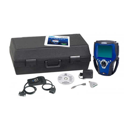
- Page 1 Genisys EVO™ User Guide...
-
Page 2: Important Notices
IMPORTANT NOTICES SAFETY DEFINITIONS Follow all DANGER, WARNING, IMPORTANT, and Note messages in this manual. These safety messages are defined and formatted as follows: DANGER or WARNING: Means you risk bodily harm and /or possible loss of life. IMPORTANT: Means the information demands special attention or that you risk damage to the vehicle or the tool. -
Page 3: Table Of Contents
Contents IMPORTANT NOTICES ............ii General Information . - Page 4 Contents Diagnostic Trouble Codes ......... . 27 Overview.
- Page 5 Contents Brake Bleed Sequence (ABS) ............62 Vehicle Information .
- Page 6 Safety Precautions DANGER: When an engine is operating, keep the service area WELL VENTILATED or attach a building exhaust removal system to the engine exhaust system. Engines produce carbon monoxide, an odorless, poisonous gas that causes slower reaction time and can lead to serious personal injury or loss of life.
-
Page 7: General Information
1: General Information Introduction The scan tool is an easy-to-use tool for reading infor- When you turn the scan tool on, the Application mation from a vehicle’s electronic control units. Manager screen displays icons (or a menu) for selecting the software applications in the scan With the tool properly connected to a vehicle’s data tool as shown and described below. -
Page 8: Component Descriptions
1: General Information Component Descriptions Component Descriptions Scan Tool Front View LCD Screen — displays the menus and data screens. (Also displays a battery charge level indicator at the top of the screen when the scan tool is turned on.) Variable Function Keys —... - Page 9 1: General Information Component Descriptions Back View Top View Figure 1.6: Classic Scan Tool Top View Figure 1.5: Scan Tool Back View Stand — flips out for setting the scan tool in an upright position. Add-On Module Compartment — holds an add-on hardware module such as the Scope and Gas M-P modules.
- Page 10 1: General Information Component Descriptions Side Views Memory Card Slot with Cover — holds the System Memory Card (DO NOT REMOVE MEMORY CARD UNLESS PERFORMING UPDATES TO CARD). PC Card Slot — holds an interface card for devices such as a modem, Ethernet network, and wireless communications.
-
Page 11: Compact Disc (Cd)
1: General Information Component Descriptions Compact Disc (CD) PC Card (optional) Figure 1.10: NGIS Software Suite CD Figure 1.12: Wireless PC Card The NGIS Software Suite contains a PC software The PC card is an optional interface card for the application that you use to download software from Classic Scan Tool. -
Page 12: Dlc Cables
1: General Information Component Descriptions DLC Cables Add-On Hardware Modules (optional) The DLC cable connects the scan tool to the vehi- When you purchase the InfoTech / Scope or Gas M-P soft- cle’s data link connector (DLC). The cable used ware applications, you receive an add-on hardware depends on the type of vehicle being tested. -
Page 13: Software Descriptions
Refer to User Interface Selection available periodically on the Internet at www.geni- page 80 sysotc.com. For complete instructions, refer to System 3.0 Upgrade (OTC P/N 543999) or NGIS Software Appli- cation Installation and Updates (OTC P/N 551254). Scan Tool User Guide... - Page 14 1: General Information Software Descriptions Scan Diagnostic Applications Repair Information Applications When you select Scan Diagnostics from the Applica- When you select Repair Information from the Appli- tion Manager screen (Figure 1.20 page 7), the cation Manager screen (Figure 1.20 page 7), the Scan Diagnostics screen appears, as shown in the...
- Page 15 1: General Information Software Descriptions Diagnostic Toolbox Applications Playback Function When you select Diagnostic Toolbox from the Appli- When you select Playback from the Application cation Manager screen (Figure 1.20 page 7), the Manager screen (Figure 1.20 page 7), the Events Diagnostic Toolbox screen appears, as shown to Playback screen appears, as shown below.
- Page 16 1: General Information Software Descriptions System Setup Functions When you select System Setup from the Application Man- This screen contains options for viewing information Figure 1.20 about the scan tool and adjusting default settings for ager screen ( page 7), the System Setup the scan tool as follows: screen appears, as shown below.
-
Page 17: User Guide Instructions
NGIS Software Suite CD installation (refer to NGIS Software Application Installation and Updates, OTC p/n 543998). To open a User Guide, double-click the User Guide icon on the Windows desktop, select a language, and then select a User Guide. - Page 18 1: General Information Software Descriptions Notes Scan Tool User Guide...
-
Page 19: Setup
When the scan tool is not connected to a vehicle, the open the protective HIP door. scan tool can be powered with an AC/DC external power adapter (OTC P/N 3421-04) or the internal Slide the locking bars out on the hardware module (you may need to hold them out). -
Page 20: Adjust Default Settings
2: Setup Adjust Default Settings Adjust Default Settings Use the System Setup functions to view information about the scan tool and adjust default settings for the scan tool as follows: NOTE: Temperature or lighting may affect the brightness of the scan tool screen. If necessary, use the Contrast Adjust function to adjust the screen for working conditions. -
Page 21: Scan Diagnostics Applications
3: Scan Diagnostics Applications Overview When you select Scan Diagnostics from the Applica- To perform scan diagnostic tests, you select an tion Manager screen (Figure 3.4 page 16), the application from the Scan Diagnostics screen, Scan Diagnostics screen appears, as shown in the enter vehicle information into the scan tool, connect examples below. -
Page 22: Test Startup And Vehicle Connection
3: Scan Diagnostics Applications Test Startup and Vehicle Connection Test Startup and Vehicle Connection This section includes the following steps: From the Scan Diagnostics screen, select an application and press the ENTER key. Step 1: Enter the Vehicle Information (below) •... - Page 23 3: Scan Diagnostics Applications Test Startup and Vehicle Connection With the Vehicle Identification screen displayed To reuse saved information for a vehicle already (Figure 3.6 page 16), do one of the following: tested, do the following: • To enter new information for a vehicle, go to Press the Reuse function key.
-
Page 24: Step 2: Connect The Cable
3: Scan Diagnostics Applications Test Startup and Vehicle Connection With the Required Cables displayed on the Vehicle To connect the cable, follow these steps: Identification screen, make the required cable Locate the required cable and any SSI or cable connections as shown on the screen. For specific adapter as required. -
Page 25: Step 3: View The Obd Ii Quick Test Results
3: Scan Diagnostics Applications Test Startup and Vehicle Connection Step 3: View the OBD II Quick Test Connect the cable’s DLC connector to the vehicle’s DLC. Results After you connect the cable and press the ENTER key on the scan tool, use the following steps if the Quick Test results screen appears. -
Page 26: Step 4: Select The Diagnostic Function
3: Scan Diagnostics Applications Test Startup and Vehicle Connection Step 4: Select the Diagnostic Function After you connect the cable and press the ENTER • Integrated Diagnostics Scan / Gas to view exhaust gas readings (CO, CO2, HC, O2, key on the scan tool, use the following steps if either NOX, AFR) along with the sensor and switch a Message screen or a Diagnostic Menu screen datastream readings. -
Page 27: Quick Dtc Scan (Supported Systems)
4: Quick DTC Scan (Supported Systems) The Quick DTC Scan for Supported Systems function does a quick check for diagnostic trouble codes (DTCs) in the ECU being tested (primary system) and any other ECUs that can be read (OBD-II and other secondary systems), and then displays a report of any DTCs found. -
Page 28: Dtc Related Repair Information
4: Quick DTC Scan (Supported Systems) DTC Related Repair Information DTC Related Repair Information When you select (highlight) the line for a DTC, if there is additional information available about the DTC, the status bar displays the message Press ENTER to view DTC related information. To view DTC information, follow these steps: Follow the steps in the Basic Test Procedure... -
Page 29: Automated System Test Tm
5: Automated System Test The Automated System Test™ does an automatic test of the ECU being tested (primary system) and any other ECUs (secondary systems) that can be read, does an OBD-II test (if OBD-II), and then displays a summary of the test results. From the summary, you can view live data and detailed test results, such as DTC descriptions and related repair information, datastream snapshots,... -
Page 30: System Test Details
5: Automated System Test System Test Details System Test Details Press the Detail function key (Figure 5.2 page to display details for the test items. With the Automated System Test, System Test Details screen displayed (Figure 5.3), you can select individual lines to view additional information about each test item. -
Page 31: Datastream Snapshots
5: Automated System Test System Test Details Datastream Snapshots Freeze Frame Data (Mode 2) When you select (highlight) the line for a datastream When you select (highlight) the line for a freeze page 24), if you can page 24), if you can snapshot (see Figure 5.3 frame item (see... -
Page 32: Component Tests (Mode 6)
5: Automated System Test System Test Details Non-Continuous Tests (Mode 6) Oxygen Sensor Tests (Mode 5) When you select (highlight) the line for a failed Non- The System Test Details screen (Figure 5.3 page (Figure 5.3 page 24), if you can view 24) may include oxygen sensor test results. -
Page 33: Diagnostic Trouble Codes
6: Diagnostic Trouble Codes Overview Read Codes The Diagnostics Trouble Codes functions let you The Read Codes procedure varies for each vehicle read, review, and clear diagnostic trouble codes being tested. This section includes the following (DTCs) for a vehicle. Read Codes procedures: Quick DTC Scan NOTE: Optionally, you can use... - Page 34 6: Diagnostic Trouble Codes Read Codes Do one of the following: • If the Read Codes menu screen appears (Figure 6.4), go to step 4. • If the DTC Information screen appears (Figure 6.5), go to Step 6. • If the Freeze Frame Selection screen appears, go to Freeze Frame (OBD II) page...
- Page 35 6: Diagnostic Trouble Codes Read Codes Freeze Frame (OBD II) • Failure Records —datastream “snapshots” automatically recorded by the ECU that show The Freeze Frame function lets you view datastream actual data values at the time DTC(s) occurred “snapshots” that were automatically recorded by the •...
- Page 36 6: Diagnostic Trouble Codes Read Codes Code History (Chrysler/Jeep) Trip Counts (Chrysler/Jeep) The Code History function shows how many times The Trip Counts function tells you how many “trips” the engine has been started since each fault was first have occurred since the DTCs were last cleared. detected.
- Page 37 6: Diagnostic Trouble Codes Read Codes KOEO Self Test (Ford / Mazda) Self-Diagnostics (Ford / Mazda) The KOEO Self Test is a key-on, engine-off, DTC- The Self-Diagnostic function lets you manually acti- reading function that lets you read MECS slow codes vate system tests that check for DTCs.
- Page 38 6: Diagnostic Trouble Codes Read Codes Options (Ford) Wait for the test to start. While the test runs, the State (of the actuators) remains active, any special The Options function lets you test the function of the instructions appear on the screen, and a timer counts down the time remaining for the test.
- Page 39 6: Diagnostic Trouble Codes Read Codes Idle Air Adjust Wiggle Test The Idle Air Adjust function checks the status of the The Wiggle Test function lets you check for intermit- base idle RPM. tent breaks in connections and for open or short circuits by manually wiggling vehicle wires.
- Page 40 6: Diagnostic Trouble Codes Read Codes Failure Records (GM / Saturn / Isuzu) The Failure Records function lets you view datastream “snapshots” that were automatically recorded by the ECU when DTC(s) occurred. By viewing the actual data values from the time of a fault, you may be able to determine what caused the fault.
-
Page 41: Read Codes Only
6: Diagnostic Trouble Codes Read Codes Read Codes Only DTC Status (GM / Saturn / Isuzu) The DTC Status function lets you view information about Use these steps to read DTCs for vehicles that allow DTCs that have occurred a predetermined number of reading of codes as one procedure and viewing of times, such as pass or fail this ignition cycle, times failed, codes as a separate procedure (review). -
Page 42: Read Flash Codes
6: Diagnostic Trouble Codes Read Codes Read Flash Codes Use the connector location and DTC retrieval procedure to read the flash codes from the vehicle. Use these steps if a vehicle requires that you read When you know the codes, press the ENTER key on diagnostic trouble codes by visually viewing them as the scan tool. -
Page 43: Review Codes
6: Diagnostic Trouble Codes Review Codes Review Codes The Review Codes function lets you view DTCs read from the selected ECU. This function displays DTCs only after you have used a function that reads codes, such as Read Codes, KOEO Self-Test, Self-Diag- nostics, Output State Test, and Wiggle Test. -
Page 44: Clear Codes
6: Diagnostic Trouble Codes Clear Codes Clear Codes After reading and / or reviewing the diagnostic trou- ble codes, use the following steps to clear the codes from the vehicle. If Clear Codes is not an available menu option, consult the manufacturer’s service manual for the correct “clear code”... -
Page 45: Datastream
7: Datastream The Datastream function lets you view live data from a vehicle’s electronic control unit (ECU). This chapter describes how to use the Datastream function. Basic Datastream Procedure Use the following steps to obtain a basic understand- ing of how the Datastream function works. To use the datastream function, follow these steps: Follow the instructions in... -
Page 46: Datastream Functions
7: Datastream Datastream Functions Datastream Functions Functions Overview Record There are several functions you can use on the Data- The Record function lets you save data files to either stream screen. Most of the functions are activated the scan tool memory or a portable USB drive. with the function keys at the bottom of the screen. - Page 47 7: Datastream Datastream Functions Record to a Portable USB Drive The recording will include all data lines that are within view on the screen plus locked and graphed lines that are not in view on the screen. Optionally, If there is a portable USB Drive inserted in the scan do any of the following to select data lines to include tool’s USB port, the Record function saves data files in the recording:...
-
Page 48: Graph / Analog / Led / Digital
7: Datastream Datastream Functions Graph / Analog / LED / Digital About Digital Display The Graph/ Analog / LED / Digital function lets you When a line is displayed as Digital, its reading is a change the display type for each line on the word or a number as shown for all the lines in Figure Datastream screen. - Page 49 7: Datastream Datastream Functions About Graph Display About Analog Display If a selected line’s data reading is a number (usually When a selected line’s data reading is displayed as 7.7), you can use the Analog a sensor reading), you can use the Graph function a graph (seeFigure key to display the line’s data as a graph.
-
Page 50: Lock
7: Datastream Datastream Functions Lock To Top The Lock function lets you “lock” selected data lines The To Top function lets you move a selected data so they are always included when recording and line to the top of the Datastream screen. printing, even if they are below the viewable area of NOTE: You can also use the Sort function to rearrange the screen. -
Page 51: Freeze Data
7: Datastream Datastream Functions Freeze Data Pathfinder The Freeze Data function lets you “freeze” the data The Pathfinder function on the Datastream screen’s display on the Datastream screen and lets you view More menu provides quick access to the Pathfinder past data frame-by-frame. -
Page 52: Print
7: Datastream Datastream Functions Print Zoom The Print function on the Datastream screen’s More The Zoom function on the Datastream screen’s More menu lets you print the data currently displayed on menu lets you magnify the view of each data line on the screen and any data below the viewable area of the Datastream screen. -
Page 53: Sort
7: Datastream Datastream Functions Sort The Sort function on the Datastream screen’s More menu lets you rearrange the data on the Datastream screen alphabetically or with either locked or graphed lines at the top of the screen. NOTE: You can also use the To Top function to rearrange the data lines. -
Page 54: English / Metric Units
7: Datastream Datastream Functions English / Metric Units Show / Hide LED Bar The English / Metric Units function on the The Show / Hide LED Bar function on the Datastream screen’s More menu lets you change the Datastream screen’s More menu lets you displays units of measure for the data from English to Metric, (or remove) a row of LED readings directly above the or vice versa. -
Page 55: Show / Hide Analog
7: Datastream Datastream Functions Show / Hide Analog When analog gauges are displayed at the top of the Datastream screen, the Show / Hide Analog function on the More menu lets you temporarily hide the gauges or display them again. NOTE: To originally display analog gauges, or to entirely turn them off, refer to Graph / Analog / LED / Digital... -
Page 56: Conflict
7: Datastream Remembered Settings Conflict Remembered Settings The Conflict function on the Datastream screen’s When you have the Datastream screen displayed for More menu lets you view detailed information when a vehicle and you rearrange the data lines or change two or more power control modules (PCMs) are lines to graphs, and then exit the Datastream screen, reading data for the same sensor or actuator, but the... -
Page 57: Custom Datastream
8: Custom Datastream The Custom Datastream function lets you select Select the data items to include in the Datastream display as follows: specific data items to display on the standard Datastream screen. Use the Up and Down Direction key to select an item to include in the display. - Page 58 NOTES: Scan Tool User Guide...
-
Page 59: Integrated Diagnostics - Scan / Gas
9: Integrated Diagnostics - Scan / Gas The Integrated Diagnostics - Scan / Gas function lets you views sensor and switch live data readings on the same screen as exhaust gas readings (CO, CO2, HC, O2, NOX AFR). NOTE: The Integrated Diagnostics option works only if the Gas M-P application is unlocked with a Smart Card and the Gas M-P hardware is used. - Page 60 9: Integrated Diagnostics - Scan / Gas Figure 9.5: Gas Correlation Time Shift Screen Use the Up or Down Direction key to enter the number of seconds to shift the data (this is the number of seconds you counted in step a; 10 to 12 seconds is average).
-
Page 61: Pathfinder Troubleshooting
10: Pathfinder Troubleshooting Repair Trac™ The Pathfinder Troubleshooting function lets you access the Pathfinder Troubleshooting software functions from within the Scan Diagnostics applica- The Repair Trac™ option lets you access the Repair tions. This option lets you view vehicle-specific infor- Trac software from within the Scan Diagnostic appli- mation for some vehicles. -
Page 62: Fast Fixes
10: Pathfinder Troubleshooting Fast Fixes Fast Fixes Torque Specifications The Fast Fixes option lets you access the Fast Fixes The Torque Specifications option lets you view a software from within the Scan Diagnostics applica- diagram and description of torque specifications for tions. -
Page 63: Oil Light Reset Test Procedure
10: Pathfinder Troubleshooting Oil Light Reset Test Procedure Oil Light Reset Test Procedure Tune Up Specifications The Oil Light Reset Test Procedure option lets you The Tune Up Specifications option lets you view a view a description of the oil light reset test procedure description of tune up specifications for the vehicle. -
Page 64: Code Information
10: Pathfinder Troubleshooting Code Information Code Information When finished, use the EXIT key to return. The Code Information option lets you view informa- tion for Diagnostic Trouble Codes for a vehicle being tested. Follow the steps in Basic Procedure page 55 display the Pathfinder Troubleshooting screen (see Figure 10.1). -
Page 65: Symptoms
10: Pathfinder Troubleshooting Symptoms Symptoms Data/Sensor Information The Symptoms option lets you view possible causes The Data / Sensor Information function lets you view and TSB numbers for specific malfunction symp- vehicle-specific, sensor and switch descriptions and toms. typical data values. Follow the steps in Basic Procedure page 55... -
Page 66: Tsb References
10: Pathfinder Troubleshooting TSB References TSB References PCM Connector Pin Information (B.O.B) The TSB References option lets you look up the numbers and titles of technical service bulletins for a The PCM Connector Pin Information (B.O.B.) option vehicle. lists test values for the sensors located at the break- Follow the steps in Basic Procedure page 55... -
Page 67: Specifications
10: Pathfinder Troubleshooting Specifications Specifications Component Location The Specifications option lets you view tune-up, The Component Location option lets you view a engine, and system specifications for a vehicle. description of the computer and connector locations for a vehicle. Follow the steps in Basic Procedure page 55 display the Pathfinder Troubleshooting screen (see... -
Page 68: Brake Bleed Procedure (Abs)
10: Pathfinder Troubleshooting Brake Bleed Procedure (ABS) Brake Bleed Procedure (ABS) Brake Bleed Sequence (ABS) The Brake Bleed Procedure option lets you view The Brake Bleed Sequence option lets you view a instructions for bleeding a vehicle’s brakes. description of the correct sequence for bleeding a vehicle’s brakes. -
Page 69: Vehicle Information
11: Vehicle Information Specifications The Vehicle Info function lets you view vehicle- specific information for Specifications, Related TSBs, System Type, and PROM Identification. The Specifications option lets you view specifica- tions for a selected control module (ECU). Follow the steps in Basic Procedure to display the Basic Procedure... -
Page 70: Tsb References
11: Vehicle Information TSB References TSB References System Type The TSB References option lets you look up the The System Type option lets you view the vehicle numbers and titles of technical service bulletins. description. Follow the steps in Basic Procedure page 63 Follow the steps in Basic Procedure... -
Page 71: Prom Id / Controller Id
12: PROM ID / Controller ID PROM ID (GM) Controller ID For some GM vehicles, the Programmable Read- The Controller ID function displays identification Only Memory Identification (PROM ID) function information about the selected ECU (Audi and displays the PROM ID number and any additional Volkswagen). - Page 72 NOTES: Scan Tool User Guide...
-
Page 73: Diagnostic States (Gm)
13: Diagnostic States (GM) For some older GM vehicle engine ECUs, the Diag- Select a Mode and press the ENTER key. nostic States function lets you place a vehicle in special test modes (states). The Road Mode is normally used for diagnostic testing and three addi- tional modes are available to check codes, serve as a backup fuel setting, or function as a service setting as follows:... - Page 74 NOTES: Scan Tool User Guide...
-
Page 75: Post Collision Test (Airbag)
14: Post Collision Test (Airbag) The Post Collision Test function is a preset test for testing air bags after repair. To perform a Post Collision Test, follow these steps: Perform the steps in Test Startup and Vehicle Connection page 16 to enter the vehicle informa- tion and display the Diagnostic Menu screen. - Page 76 NOTES: Scan Tool User Guide...
-
Page 77: Special Tests (Actuator Tests)
15: Special Tests (Actuator Tests) Overview Basic Special Test Procedure The Special Tests function lets you perform special The special tests vary for each vehicle, year, and bi-directional diagnostic tests on vehicle systems module (Engine, Transmission, ABS, etc.). This and components. The tests let you use the scan tool section provides basic steps for the special tests. -
Page 78: Special Test Screen Examples
15: Special Tests (Actuator Tests) Special Test Screen Examples Special Test Screen Examples Bi-Directional Control Screen There are two basic types of special test screens: instructional and bi-directional control. Examples Instructional Screen Example The bi-directional control screens vary in appear- ance, but they all allow you to manually control the Instructional screens contain step-by-step instruc- vehicle’s relays, solenoids, lamps, and other compo-... - Page 79 15: Special Tests (Actuator Tests) Special Test Screen Examples Basic Multiple Component Control Screen Solenoid, Relay Controls Screen The following screen is the basic manual control The following screen is the basic manual control screen for multiple components. This screen allows screen for a solenoid and enable relay.
- Page 80 15: Special Tests (Actuator Tests) Special Test Screen Examples Automatic Test Screen Activate/Deactivate Screen The following screen is an example of an automatic The following screen is an example of a manual test screen.You press the Start function key to begin control screen with a toggle Activate/Deactivate the automatic test.
-
Page 81: Playback
16: Playback The Playback function lets you view data recorded to NOTE: The Events to Playback list holds 25 recordings. When the list is full, old recordings automatically delete as the scan tool’s memory card with the Datastream you make new recordings. To prevent a recording from Record function (see page 40), DTC-Triggered... -
Page 82: Copy Files To / From Usb Drive
16: Playback Copy Files To / From USB Drive Copy Files To / From USB Drive The Copy Files function lets you copy saved files to Select an option and press the ENTER key as follows: and from a portable USB Drive for either temporary or permanent storage. -
Page 83: System Setup
17: System Setup The System Setup functions let you adjust default Refer to the following sections: settings and view information about the scan tool. • Contrast Adjust page 77 • Printer Selection page 78 Basic Procedure • Printer Header page 78 •... -
Page 84: Printer Selection
17: System Setup Printer Selection Printer Selection Printer Header The Printer Selection function lets you select a The Print Header function lets you set up a heading printer for printing from the scan tool. for reports that you print from the scan tool. Follow the steps in Basic Procedure page 77... -
Page 85: Unit Defaults
17: System Setup Unit Defaults Unit Defaults Revision Levels The Unit Defaults function lets you set the date, time, The Revision Levels function displays software units-of-measure, and automatic shut down time. It version numbers (for use when calling technical also lets you turn the audible beep and print header support). -
Page 86: Technical Support
17: System Setup Technical Support Technical Support Color Scheme Selection The Technical Support function displays technical The Color Scheme Selection function lets you set the support information. color of the background and text that appears on the scan tool screens. Follow the steps in Basic Procedure page 77... -
Page 87: Hardware Tests
17: System Setup Hardware Tests Hardware Tests Disk Usage The Hardware Tests function lets you test the LCD The Disk Usage function lets you view details about screen, keypad keys, backlight, beeper, and Smart the scan tool memory size and usage. cable, and lets you view the time clock and serial Follow the steps in Basic Procedure... - Page 88 NOTES: Scan Tool User Guide...
-
Page 89: Printing
You can print diagnostic trouble codes, sensor data, follow these steps: and report summary data from the scan tool to a Hewlett Packard infrared printer (OTC P/N 3157). To print data to an infrared printer, follow these steps: Turn on the battery-powered infrared printer. - Page 90 NOTES: Scan Tool User Guide...
-
Page 91: Technical Service
Order Information Replacement and optional parts can be ordered directly from your SPX authorized tool supplier. Your order should include the following information: • quantity • part number • item description Technical Service If you have any questions on the operation of the product, please call (800) 533-6127. Repair Service When sending your SPX electronic product in for repair, please include the following information: •... - Page 92 2008 SPX Corporation. All rights reserved 11/11/08 Part Number 551252...
Need help?
Do you have a question about the Genisys EVO and is the answer not in the manual?
Questions and answers