Table of Contents
Advertisement
Quick Links
Advertisement
Table of Contents

Related Manuals for ASROCK iEP-5000G Series


Summary of Contents for ASROCK iEP-5000G Series
- Page 1 Series User Manual Version 1.0 Published April 2022...
- Page 2 ASRock Industrial has been advised of the possibility of such damages arising from any defect or error in the documentation or product.
- Page 3 Important Safety Instructions For user safety, please read and follow all instructions, Warnings, Cautions, and Notes marked in this manual and on the associated device before handling/operating the device, to avoid injury or damage. 1. Read these safety instructions carefully. 2.
- Page 4 FSP065-RBBN3, FSP/FSP120-ABAN3) suitable for use at TMA 40 °C (104 °F) min., and the output is rated 19 Vdc, 3.42A/6.32A min., ES1. If you need further assistance, contact ASRock Industrial for additional information. Replaceable batteries CAUTION : RISK OF EXPLOSION IF BATTERY IS REPLACED BY AN INCORRECT TYPE.
- Page 5 CAUTION The equipment is equipped with a battery-powered real-time clock circuit. There is a risk of explosion if a battery is incorrectly replaced. Replace only with same or equivalent type as recommended by the manufacturer. Discard all used batteries according to the manufacturer’s instructions.
- Page 6 States and other countries. Contact Information If you need to contact ASRock Industrial or want to know more about ASRock Industrial, you’re welcome to visit ASRock Industrial’s website at www.asrockind.com ; or you may contact your dealer for further information.
-
Page 7: Table Of Contents
Contents Chapter 1 Introduction Package List Order Information Optional Items Product Specifications Block Diagram Chapter 2 Product Overview Side View Top View Inside View Position Chapter 3 Hardware Installation How to Remove the Front Cover How to Install the WiFi Module (M.2 Key E Socket (2230)) (Optional) How to Install the 4G LTE / 5G module (M.2 Key B Socket (3042/3052)) (Optional) - Page 8 3.10 How to Install the 5G Module Heatsink (Optional) Chapter 4 Motherboard (DSB-1000-WT) Motherboard Layout Motherboard Specifications Jumpers Setup Onboard Headers and Connectors Chapter 5 UEFI Setup Utility Introduction Main Screen Advanced Screen Hardware Health Event Monitoring Screen Security Screen Boot Screen Exit Screen...
-
Page 9: Chapter 1 Introduction
Series Chapter 1 Introduction Because the hardware specifications might be updated, the content of this documentation will be subject to change without notice. 1.1 Package List iEP-5000G-000 Series • 1 x iEP-5000G-000/iEP-5001G-000 • 1 x DSB-1000-WT/DSB-1001-WT (pre-installed motherboard) • 3 x Screws for M.2 Module • 1 x M.2 M key (2280) Storage Heatsink... -
Page 10: Order Information
1.2 Order Information Model Name Description iEP-5000G-000 Intel® Atom® x6425RE Processor, w/o RAM, SSD, ADAPTER iEP-5001G-000 Intel® Atom® x6212RE Processor, w/o RAM, SSD, ADAPTER iEP-5000G-001 Intel® Atom® x6425RE Processor, Support PoE, w/o RAM, SSD, ADAPTER iEP-5001G-001 Intel® Atom® x6212RE Processor, Support PoE, w/o RAM, SSD, ADAPTER 1.3 Optional Items Model Name... -
Page 11: Product Specifications
Series 1.4 Product Specifications iEP-5000G Series Barebone For iEP-5000G Series : Intel® Elkhart Lake SoC Processors x6425RE, QC, 1.9GHz, 12W For iEP-5001G Series : Intel® Elkhart Lake SoC Processors x6212RE, DC, 1.2GHz, 6W Chipset BIOS AMI SPI 256 Mbit... - Page 12 Audio Realtek ALC897 HD codec CANBus 1 x CANBus connector supports up to 2 CANBus devices via (Option) additional cable iEP-5000G-000 Series Top I/O 4 x Antenna Hole, 1 x VGA, 1 x Serial Port, 1 x Digital I/O iEP-5000G-001 Series 2 x LAN Port, 1 x VGA, 1 x Serial Port, 1 x Digital I/O iEP-5000G-002 Series 2 x Antenna Hole, 1 x CANBus, 1 x VGA, 1 x Serial Port,...
-
Page 13: Block Diagram
Series 1.5 Block Diagram... -
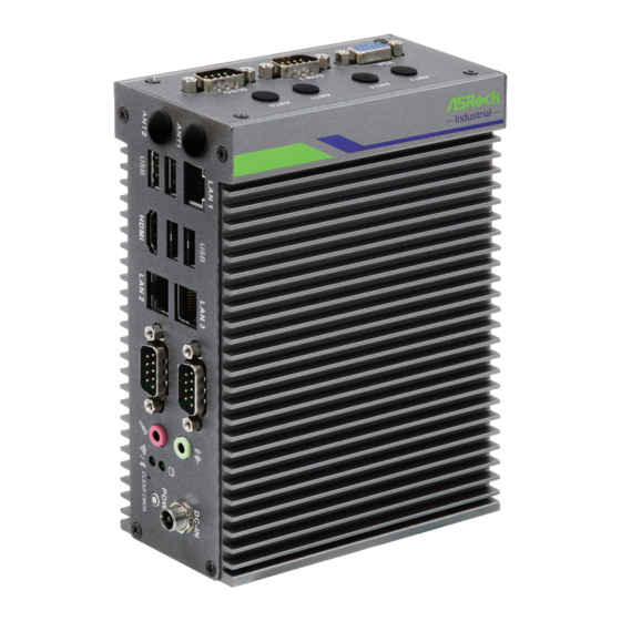
Page 14: Chapter 2 Product Overview
Chapter 2 Product Overview This chapter provides diagrams showing the location of important components of the iEP-5000G Series. 2.1 Side View 11 12 13 14 Description Antenna Hole LAN Port * USB 2.0 Serial Port Audio (Line-Out) HDD LED** DC-IN Connector USB 3.2 Gen2... - Page 15 Series * There are two LEDs on the LAN port. Please refer to the table below for the LAN port LED indications. ACT/LINK LED SPEED LED LAN Port Activity / Link LED Speed LED Status Description Status Description No Link...
-
Page 16: Top View
2.2 Top View iEP-5000G-000 Series Description Antenna Hole Serial Port Digital I/O iEP-5000G-001 Series Description LAN Port, each port supports IEEE 802.3AT PoE+ LAN LED Serial Port Digital I/O... - Page 17 Series iEP-5000G-002 Series Description CANBus Port Antenna Hole Serial Port Digital I/O...
-
Page 18: Inside View
M.2 M Key Socket (2280) for PCIe x2/SATAIII for storage SO-DIMM Slot SATA 3.0 Connector SO-DIMM memory, hard drive and M.2 SSD are not included with this system. 2.4 Position The iEP-5000G Series should be placed in vertical position only. -
Page 19: Chapter 3 Hardware Installation
Series Chapter 3 Hardware Installation This chapter helps you install or remove important components. 3.1 How to Remove the Front Cover 1. Remove the screws on the case. 2. Then lift up and remove the front cover. -
Page 20: How To Install The Wifi Module (M.2 Key E Socket (2230)) (Optional)
3.2 How to Install the WiFi Module (M.2 Key E Socket (2230)) (Optional) 1. Locate the WiFi Module slot on the motherboard. 2. Carefully insert the WiFi Module into the slot. 3. Tighten the screw to secure the WiFi Module to the motherboard. -
Page 21: How To Install The 4G Lte / 5G Module (M.2 Key B Socket (3042/3052)) (Optional)
Series 3.3 How to Install the 4G LTE / 5G module (M.2 Key B Socket (3042/3052)) (Optional) 1. Locate the 4G LTE/5G Module slot on the motherboard. 2. Carefully insert the 4G LTE/5G Module into the slot. 3. Tighten the screw to secure the 4G LTE/5G Module to the motherboard. -
Page 22: How To Install The M.2 Ssd With The Heasink (M.2 Key M Socket (2280))
3.4 How to Install the M.2 SSD with the Heasink (M.2 Key M Socket (2280)) 1. Gently insert the M.2 module, along the guiding tabs, into the heatsink bracket.. 2. Remove the membrane from heatsink. Align the heatsink to the edge of the bracket and press down the heatsink into the bracket. - Page 23 Series 4. Tighten the screw to secure the M.2 module and the heatsink to the motherboard.
-
Page 24: How To Install The Memory Modules And The Heatsinks
3.5 How to Install the Memory Modules and the Heatsinks For dual channel configuration, you always need to install identical (the same brand, speed, size and chip-type) DDR4 SO-DIMM pairs. The SO-DIMM only fits in one correct orientation. It will cause permanent damage to the motherboard and the DIMM if you force the DIMM into the slot at incorrect orientation. - Page 25 Series 3. Remove the membrane from heatsink. Then paste the heatsink onto the module.
-
Page 26: How To Install The 2.5-Inch Hard Drive (Optional)
3.6 How to Install the 2.5-inch Hard Drive (Optional) 1. Remove the screws on the case. Then lift up and remove the front cover. 2. Attach the HDD to the HDD bracket and secure it with four screws. Then connect the SATA cable to the HDD. - Page 27 Series 3. Attach the HDD assembly to the front cover and secure it with four screws. Then connect the SATA Data and Power Cable to the motherboard. 4. Then reinstall the front cover.
-
Page 28: How To Install The Sim Card And The Micro Sd Card
3.7 How to Install the SIM Card and the Micro SD Card 1. Release the screws on the iEP-5000G Series and remove the SIM/Micro SD Card slot cover.. 2. With the gold contacts facing front, carefully insert the SIM Card or the SD Card into the designated slot until it clicks.. - Page 29 Series 3. Place the cover back and secure it to the iEP-5000G Series with screws.
-
Page 30: How To Install The Wall Mounting Bracket
3.8 How to Install the Wall Mounting Bracket 1. Attach the wall mounting brackets to the iEP-5000G Series and secure it with screws.. 2. Then you can attach the iEP-5000G Series to the wall with screws. - Page 31 Series Dimension of the iEP-5000G Series with Wall Mounting Bracket Installed 100mm 86mm 42mm 53mm Wall Mounting Bracket is not provided by default. Please purchase it seperately if needed.
-
Page 32: How To Install The Din Rail Mounting Bracket (Optional)
3.9 How to Install the Din Rail Mounting Bracket (Optional) 1. Attach the Din Rail Bracket to the iEP-5000G Series and secure it with screws. 2. Then you can place the iEP-5000G Series to the Din Rail. Din Rail Bracket is not provided by default. Please purchase it seperately if needed. -
Page 33: How To Install The 5G Module Heatsink (Optional)
Series 3.10 How to Install the 5G Module Heatsink (Optional) 1. Remove the membranes on the both sides of the 5G module heatsink. 2. Attach the 5G Module Heatsink to the internal side of the front cover and secure it with screws. -
Page 34: Chapter 4 Motherboard (Dsb-1000-Wt)
Chapter 4 Motherboard (DSB-1000-WT) 4.1 Motherboard Layout Top Side:... - Page 35 Series Rear Side:...
- Page 36 1 : SATA3 Connector (SATA3_1) 2 : SATA Power Output Connector (SATA_PWR1) 3 : CAN Connector (CAN1_2) 4 : M.2 Key-E Socket (M2_E1) 5 : M.2 Key-B Socket (M2_B1) 6 : ATX/AT Mode Jumper (SIO_AT1) 7 : Clear CMOS Header (CLRMOS2) 8 : SMBUS Connector (SMBUS1) 9 : DACC Jumper (DACC1) 10 : M.2 Key-M Socket (M2_M1)
-
Page 37: Motherboard Specifications
Series 4.2 Motherboard Specifications ® Processor Intel ELK CPU 1 x HDMI 2.0b Video 1 x VGA System Core Support 4K (4096x2160) @ 60Hz 2 x DDR4 3200MHz SO-DIMM, up to 32GB Memory (In-Band ECC) 2 x GbE (2 x Maxlinear GPY115, 1 TSN... - Page 38 6-36 VDC, 80V Surge Protection DC Input Supports Latch Adaptor Power Supply AC to DC 65W AC-DC with Latch adapter (Option) Adaptor 1 x Micro SD card slot, supports SDXC SD Slot V3.01 for 64GB~2TB Windows 10 (No TSN support over Win 10) OS Support Linux (YOCTO w/ TSN, Ubuntu) Storage Device...
-
Page 39: Jumpers Setup
Series 4.3 Jumpers Setup The illustration shows how jumpers are setup. When the jumper cap is placed on pins, the jumper is “Short”. If no jumper cap is placed on pins, the jumper is “Open”. The illustration shows a 3-pin jumper whose pin1 and pin2 are “Short”... -
Page 40: Onboard Headers And Connectors
4.4 Onboard Headers and Connectors Onboard headers and connectors are NOT jumpers. Do NOT place jumper caps over these headers and connectors. Placing jumper caps over the headers and connectors will cause permanent damage of the motherboard! SATA3 Connector This Serial ATA3 (SATA3) SATA3_1 connector supports SATA data (SATA3_1: see p.8, No. - Page 41 Series 4.5 Expansion Slots (M.2 Sockets) There are 3 M.2 sockets on this motherboard. M.2 Key-M Socket (M2_M1): M.2 Key M Socket (2242/2260/2280) supports NVMe with PCIex2/SATA for Storage. M.2 Key-E Socket (M2_E1): M.2 Key E Socket (2230) for Wireless M.2 Key-B Socket (M2_B1):...
-
Page 42: Chapter 5 Uefi Setup Utility
Chapter 5 UEFI Setup Utility 5.1 Introduction This section explains how to use the UEFI SETUP UTILITY to configure your system. The UEFI chip on the motherboard stores the UEFI SETUP UTILITY. You may run the UEFI SETUP UTILITY when you start up the computer. Please press <F2>... -
Page 43: Main Screen
Series 5.1.2 Navigation Keys Please check the following table for the function description of each navigation key. Navigation Key(s) Function Description Moves cursor left or right to select Screens Moves cursor up or down to select items + / - To change option for the selected items <Enter>... -
Page 44: Advanced Screen
5.3 Advanced Screen In this section, you may set the configurations for the following items: CPU Configu- ration, Chipset Configuration, Intel(R) Time Coordinated Computing, Storage Con- figuration, NVMe Configuration, Super IO Configuration, ACPI Configuration, USB Configuration, Trusted Computing and PSE Configuration. Setting wrong values in this section may cause the system to malfunction. - Page 45 Series 5.3.1 CPU Configuration Active Processor Cores Select the number of cores to enable in each processor package. CPU C States Support Enable CPU C States Support for power saving. It is recommended to keep C3, C6 and C7 all enabled for better power saving.
- Page 46 5.3.2 Chipset Configuration Above 4G Decoding Enable or disable 64bit capable Devices to be decoded in Above 4G Ad- dress Space (only if the system supports 64 bit PCI decoding). VT-d ® ® Use this to enable or disable Intel VT-d technology (Intel Virtualization Technology for Directed I/O).
- Page 47 Series 5.3.3 Intel(R) Time Coordinated Computing Intel TCC Mode Enable or Disable Intel(R) TCC Mode. When enabled, this will modify system settings to improve real-time performance. The full list of settings and their current state are displayed below when Intel(R) TCC mode is en- abled.
- Page 48 5.3.4 Storage Configuration SATA Controller(s) Use this item to enable or disable the SATA Controller feature. SATA Mode Selection Use this to select SATA mode. The default value is [AHCI Mode]. AHCI (Advanced Host Controller Interface) supports NCQ and other new features that will improve SATA disk perfor- mance but IDE mode does not have these advantages.
- Page 49 Series 5.3.5 NVMe Configuration...
- Page 50 5.3.6 Super IO Configuration COM1 Configuration Use this to set parameters of COM1. Type Select Use this to select COM1 port type: [RS232], [RS422] or [RS485]. COM2 Configuration Use this to set parameters of COM2. Type Select Use this to select COM2 port type: [RS232], [RS422] or [RS485]. COM3 Configuration Use this to set parameters of COM3.
- Page 51 Series 5.3.7 ACPI Configuration Suspend to RAM Use this item to select whether to auto-detect or disable the Suspend-to- RAM feature. Select [Auto] will enable this feature if the OS supports it. Onboard LAN Power On Use this item to enable or disable onboard LAN to turn on the system from the power-soft-off mode.
- Page 52 5.3.8 USB Configuration USB Power Control Use this option to control USB power.
- Page 53 Series 5.3.9 Trusted Computing Security Device Support Enable or disable BIOS support for security device.
- Page 54 5.3.10 PSE Configuration PSE Controller Use this to enable or disable Programmable Service Engine (PSE) device. Shell Enable or diaable shell. Onboard LAN1 This allows you to enable or disable the Onboard LAN1 feature. Smart-AZ Enable or diaable Smart-AZ. Onboard LAN2 This allows you to enable or disable the Onboard LAN2 feature.
-
Page 55: Hardware Health Event Monitoring Screen
Series 5.4 Hardware Health Event Monitoring Screen In this section, it allows you to monitor the status of the hardware on your system, including the parameters of the CPU temperature, motherboard temperature, CPU fan speed, chassis fan speed, and the critical voltage. -
Page 56: Security Screen
5.5 Security Screen In this section, you may set, change or clear the supervisor/user password for the system. Supervisor Password Set or change the password for the administrator account. Only the ad- ministrator has authority to change the settings in the UEFI Setup Utility. Leave it blank and press enter to remove the password. -
Page 57: Boot Screen
Series 5.6 Boot Screen In this section, it will display the available devices on your system for you to config- ure the boot settings and the boot priority. Boot From Onboard LAN Use this item to enable or disable the Boot From Onboard LAN feature. -
Page 58: Exit Screen
5.7 Exit Screen Save Changes and Exit When you select this option, it will pop-out the following message, “Save configuration changes and exit setup?” Select [OK] to save the changes and exit the UEFI SETUP UTILITY. Discard Changes and Exit When you select this option, it will pop-out the following message, “Discard changes and exit setup?”...
Need help?
Do you have a question about the iEP-5000G Series and is the answer not in the manual?
Questions and answers