
Summary of Contents for bonitron Legacy M3534R-RY
- Page 1 Legacy Model M3534R-RY 40 & 85 Amp DC Bus Ride-Thru for Variable Frequency AC Drives Customer Reference Manual ● ● Web: www.bonitron.com Tel: 615-244-2825 Email: info@bonitron.com...
- Page 2 Bonitron has seen thousands of products engineered since 1962 and welcomes custom applications. With engineering, production, and testing all in the same facility, Bonitron is able to ensure its products are of the utmost quality and ready to be applied to your application.
- Page 3 RIVE PTIONS In 1975, Bonitron began working with AC inverter drive specialists at synthetic fiber plants to develop speed control systems that could be interfaced with their plant process computers. Ever since, Bonitron has developed AC drive options that solve application issues associated with modern AC variable frequency drives and aid in reducing drive faults.
-
Page 4: Table Of Contents
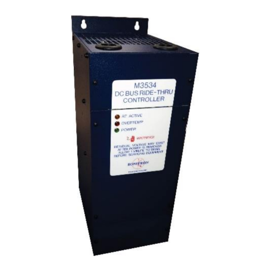
M3534R 40&85A ........................1 NTRODUCTION 1.1. Who Should Use ........................1 1.2. Purpose and Scope........................1 1.3. Manual Version and Change Record ..................1 Figure 1-1: M3534R in the K7 Chassis ..................... 1 1.4. Symbol Conventions Used in this Manual and on Equipment ..........2 ......................3 RODUCT ESCRIPTION... - Page 5 7.4.2. Minimum Capacitor Bank Voltage ....................43 7.4.3. Peak Current ..........................44 7.4.4. Capacitor Specifications ........................ 44 7.4.5. Minimum Series String ......................... 44 7.4.6. Available Joules ..........................45 7.5. Diode Sharing with a Bonitron M3534 Ride-Thru ..............46 Figure 7-1: Diode Sharing Example ....................47...
- Page 6 M3534R 40&85A This page intentionally left blank...
-
Page 7: Introduction
User’s Manual 1. I NTRODUCTION 1.1. W HOULD This manual is intended for use by anyone who is responsible for integrating, installing, maintaining, troubleshooting, or using this equipment with any AC drive system. Please keep this manual for future reference. 1.2. -
Page 8: Symbol Conventions Used In This Manual And On Equipment
M3534R 40&85A 1.4. S YMBOL ONVENTIONS SED IN THIS ANUAL AND ON QUIPMENT Earth Ground or Protective Earth AC Voltage DC Voltage Electrical Hazard - Identifies a statement that indicates a shock or electrocution hazard that must be avoided. DANGER! DANGER: Identifies information about practices or circumstances that can lead to personal injury or death, property damage, or economic loss. -
Page 9: Roduct Escription
VFD shutdowns caused by these occurrences. Bonitron’s Model M3534 series of DC Bus Ride-Thru Modules (RTM) provide protection from AC line voltage sags and outages for AC drive systems that use a fixed DC bus as with AC PWM VFDs by temporarily storing energy internally and releasing it back into the DC bus when needed. -
Page 10: Part Number Breakdown
M3534R 40&85A 2.2. P UMBER REAKDOWN Figure 2-1: Example of Part Number Breakdown M3534R E 024 DP10 AS E O D E L U M B E R Y S T E M O L T A G E A T I N G O W E R A T I N G H A S S I S... -
Page 11: General Specifications
User’s Manual 2.3. G ENERAL PECIFICATIONS Table 2-2: General Specifications Chart PECIFICATION ARAMETER AC Input Voltage 208 - 480VAC 265 - 585VDC minimum DC Output Voltage 295 - 650VDC nominal 40A – 85A Max. DC Output Current 24kW – 50kW Maximum Kilowatt Rating Maximum Sag Duration 2 seconds... -
Page 12: General Precautions And Safety Warnings
M3534R 40&85A 2.4. G ENERAL RECAUTIONS AND AFETY ARNINGS H I G H V O L T A G E S M A Y B E P R E S E N T N E V E R A T T E M P T T O O P E R A T E T H I S P R O D U C T W I T H T H E E N C L O S U R E C O V E R R E M O V E D DANGER! ... -
Page 13: Installation Instructions
User’s Manual 3. I NSTALLATION NSTRUCTIONS Installation and/or removal of this product should only be performed by a qualified electrician in accordance with National Electrical Code or local DANGER! codes and regulations. Proper installation of the Model M3534R Ride-Thru Module should be accomplished following the steps outlined below. -
Page 14: Wiring And Customer Connections
M3534R 40&85A 3.4. W IRING AND USTOMER ONNECTIONS This section provides information pertaining to the field wiring connections of the M3534R Ride-Thru Module. Actual connection points and terminal numbers of the AC Drive system will be found in the documentation provided with that system. Be sure to review all pertinent AC Drive System documentation as well as the RTM to Drive Interconnection details listed below before proceeding. - Page 15 User’s Manual dimensional outline drawing in Section 6.4 of this manual. 3.4.1.1. 3-P AC L (L1, L2, L3) HASE NPUT 40A units: The 3-phase AC Line input connections are made directly to the fuse block terminals for F1 (L1), F2 (L2), and F3 (L3). Connections can be made using 10 AWG wire.
-
Page 16: Control Interface Wiring
M3534R 40&85A 3.4.2. ONTROL NTERFACE IRING 3.4.2.1. T NPUT ONNECTIONS 40 and 85 Amp units: Test input connections may be made across TB6- 1 (Positive) and TB6-2 (Negative) of the ASB 3534R3 Control Board. Torque terminal screws to 2 lb-in max. 3.4.2.2. - Page 17 User’s Manual Figure 3-1: Typical K7 Chassis Field Connection Terminal Layout side wall) Ground Figure 3-2: Typical A9 Chassis Field Connection Terminal Layout Ground...
- Page 18 M3534R 40&85A Figure 3-3: K7 Chassis Standard Model Disable Relay 24V DISABLE Relay ─ TEST Status Figure 3-4: A9 Chassis Standard Model Disable Relay 24V DISABLE Relay ─ TEST Status...
- Page 19 User’s Manual Figure 3-5: Typical Control and Status Connections with I3 Interface TB 4 TB 5 Disable RTR Display Panel C J1 C J2...
-
Page 20: Typical Configurations
M3534R 40&85A 3.5. T YPICAL ONFIGURATIONS Figure 3-6: Typical M3534R Interconnection with Existing Drive System Note: Typical 40 Amp model shown Dwg: 060304 Rev: 20071205... - Page 21 User’s Manual Figure 3-7: Typical 85 Amp (A9 Chassis) M3534R Parallel Wiring Diagram Note: Special Option “C” must be purchased for sharing to work properly. Dwg: 060189 Rev 20070806...
- Page 22 M3534R 40&85A This page intentionally left blank...
-
Page 23: Operation
User’s Manual 4. O PERATION 4.1. F UNCTIONAL ESCRIPTION The M3534R series of Ride-Thru Modules (RTMs) employs IGBT switching technology to regulate the inverter DC bus to a preset minimum voltage level. As the incoming AC voltage level drops, the RTM “activates”, boosting a rectified DC voltage up to the minimum DC bus voltage level specified for the inverter, allowing it to “ride through”... -
Page 24: Features
M3534R 40&85A 4.2. F EATURES 4.2.1. ERMINAL TRIP See Figures 6-3 and 6-4 for physical connection locations. 4.2.1.1. C ONTROL NPUTS TANDARD ODELS The DISABLE command is connected directly to the K1 DISABLE Relay. 24V will inhibit the module from boosting. No connection allows normal operation. - Page 25 User’s Manual DP10 O ODELS WITH PTION BOARD Fault Signals are available on the 3534I3 board as described in Sec 4.2.2.4. Table 4-1: Control Status Signal Connection Details for Standard Models ERMINAL LECTRICAL ORQUE OARD UNCTION PECIFICATIONS 120VAC / .5 Amp 1kV Isolation Phoenix plug TB5 Status...
-
Page 26: Indicators
M3534R 40&85A Table 4-4: Status Signal Component Details for Models with DP10 “I3” Option TATUS IGNAL OMPONENT TATUS OARD OMPONENTS (RTA) (RTR) CTIVE EADY Jumper Contact Ratings 120mA at 350VDC 120mA at 350VDC Indicator None None 3534I3 Interface Board 3534I3 3534I3 Terminations TB4-1,2... - Page 27 User’s Manual Figure 4-1: ASB 3534R3 Control Board Features LD1 LD2 LD3 TB7 Disable PWR OT R35 Threshold TB5 – Status TB6 - Test J2 - OT J3 - RTA R30 Input TB4 - Fan Current Limit ASB 3534R3 S TATUS NDICATORS The purpose and function of each status indicator provided on the ASB...
-
Page 28: Remote Or Cabinet Door System Status Display And Test Module
M3534R 40&85A 4.2.2.2. ASB 3534I3 I NTERFACE OARD Figure 4-2: ASB 3534I3 Interface Board Features Disa 3534I3 I NTERFACE OARD UMPER The 3534I3 interface card isolates the front panel from the drive system voltage, and provides an output for remote monitoring of Ready and Active signals. - Page 29 This counter is not affected by the Reset push-button located to the right on the front face of the counter. To reset the Total RTA Cycles Counter please consult Bonitron Engineering.
-
Page 30: Startup
Some inverters can be reprogrammed to change this trip level. Bonitron typically sets the DC bus threshold to be approximately 10% below nominal level. For example, Bonitron sets all 460VAC systems to hold the 640V DC bus to 585VDC. Refer to the inverter documentation for details on adjusting its under voltage trip setting if the factory default setting is other than 15% below nominal DC bus level. -
Page 31: Operational Adjustments
ODEL M3534 R ODULES The "Threshold" voltage level is the voltage at which the Bonitron Model M3534 Ride-Thru module maintains the DC bus during a power dip. Whenever the DC bus level drops to the "Threshold" setpoint, the Ride-Thru module becomes active to regulate the DC bus voltage to the "Threshold"... -
Page 32: Determining Threshold Voltage Setpoint
HRESHOLD OLTAGE ETPOINT OADED YSTEM 1) V ERIFY PROPER INSTALLATION Ensure that the Bonitron Model M3534 Ride-Thru Module has been properly installed and wired according to all applicable system and module wiring diagrams. 2) P TEST USH THE BUTTON Push the "Test" button while monitoring the DC bus voltage. -
Page 33: Adjustment Pots
User’s Manual Subtracting the Boost voltage (100VDC) from this reading shows that the actual Threshold voltage level is 585VDC. Initiating this test on a heavily loaded system of this nature would also cause the DC bus level to rise. However, the DC bus would stop rising once current limit is reached. - Page 34 However, field calibration of this setpoint may be necessary if the AC line level is more than 7% below the nominal AC requirement listed on the RTM module nameplate. Contact Bonitron, Inc. for additional information as needed.
-
Page 35: Maintenance And Troubleshooting
ERIODIC ESTING The Bonitron Ride-Thru is designed to be low maintenance. While the amount of ride- thru time does not depend on energy storage devices that degrade over time, Bonitron still recommends a yearly test of the system in order to ensure the electronics package is operating. - Page 36 This threshold level should be approximately 10-12% below the nominal loaded inverter bus. Each Bonitron Ride-Thru should be tested under load during initial start up to verify the functionality of the test circuit and that the test does not negatively affect the process.
-
Page 37: Maintenance Items
User’s Manual 5.2. M AINTENANCE TEMS 5.2.1. APACITOR EPLACEMENT ECOMMENDATIONS 5.2.1.1. C LEANING Cleaning cycle depends entirely upon surrounding environment and quality of air inside cabinet. Cleaning off dust, debris, or chemical build-up on high voltage bus bars or other exposed components may be necessary. If cleaning is needed: 1. -
Page 38: Technical Help - Before You Call
The battery bank voltage The DC Bus voltage KVA rating of power source Source configuration Wye/Delta and grounding This information will help us support you much more quickly. Please contact us at (615) 244-2825 or through www.bonitron.com... -
Page 39: Ngineering Ata
A60Q125 / A70Q80 85ADC The codes listed in the CHX SIZE column of the table above refer to specific Bonitron chassis designs. For chassis details see the dimensional outlines in Section 6.4. For higher ratings, batteries can be added and 85 Amp units can be paralleled. -
Page 40: Fuse/Circuit Breaker Sizing And Rating
M3534R 40&85A 6.3. F IRCUIT REAKER IZING AND ATING 6.3.1. ECOMMENDED NPUT OWER IRING IZES OWER OURCE USING The following data is supplied for assistance in selecting the appropriate field wiring sizes and power source fuse ratings for the model M3534R Cabinet Mounted and Open-chassis Ride-Thru systems. -
Page 41: Dimensions And Mechanical Drawings
User’s Manual 6.4. D IMENSIONS AND ECHANICAL RAWINGS Figure 6-1: 24kW Ride-Thru K7 Chassis Dimensional Outline Dwg: 120210 Rev: 20120619... - Page 42 M3534R 40&85A Figure 6-2: M3534R 50kW A9 Chassis Dimensional Outline Dwg: 120220 Rev: 20120626...
-
Page 43: Supplemental Drawings
User’s Manual 6.5. S UPPLEMENTAL RAWINGS Figure 6-3: 3534R3 TB5 Status Signal Figure 6-4: 3534R Status Signal Schematics Dwgs: 060165 Rev: 20090615 and 070001 Rev: 20090624... -
Page 44: Recommended Spare Parts
Tables 6-6 and 6-7 list the major components for the M3534R modules. These lists are intended for use as a reference when ordering spare parts for the Ride- thru modules becomes necessary. Please remember to refer to the complete Bonitron part number when ordering parts. - Page 45 FWP-100B Semiconductor Fuse LD AMB-LENS-L05 Red lens cap LD GRN-LENS-L05 Green lens cap LD RED-LENS-L05 Amber lens cap LD RED-LENS-L05-W Neoprene Washer NOTE: Spare circuit boards are available for companies who have active personnel with training certificates on file with Bonitron.
- Page 46 M3534R 40&85A This page intentionally left blank...
-
Page 47: Appendices
7.2. I NSTALLATION ONSIDERATIONS FOR RIVE YSTEMS The following items should be considered when installing a Bonitron Ride-Thru: Inverter logic voltage must be "backed up" Most new Inverters derive logic supply from DC bus Install UPS on circuits with AC feed Any control or Interlock relays must be "backed up"... -
Page 48: Application Notes For M3534R Modules
ANK FOR FULL M3534R OUTAGE PROTECTION WITH THE Bonitron M3534R models can have energy storage devices added to cover complete outages. This involves adding a capacitor bank with an appropriate charging and discharging system. Bonitron can source complete capacitor cabinets or individual capacitors. -
Page 49: Energy Required For Outage
User’s Manual These are the definitions of the variables we will use in the following equations: �� - Capacitance at end of life ������ �� - Total capacitance of the entire cap bank ������ ������ - Total equivalent ESR for the entire cap bank ������... -
Page 50: Peak Current
M3534R 40&85A 7.4.3. URRENT The peak current from the capacitor bank will occur at the minimum voltage. This can be estimated from the equation peak For our example, 75kW = 235A peak 320Vdc 7.4.4. APACITOR PECIFICATIONS At this point, a specific capacitor's characteristics can be used. It is best to use the values that are listed at end of life for the capacitor to make sure that the storage system is sized for the eventual degradation of performance over time. -
Page 51: Available Joules
User’s Manual 7.4.6. VAILABLE OULES At this point, the available maximum joules for the string can be calculated. ∗ V Charge series CapMax �� = 8 ∗ 46�� = 368�� ��ℎ�������� The capacitor voltage at the end of the discharge �� will be given by: ������������... -
Page 52: Diode Sharing With A Bonitron M3534 Ride-Thru
M3534R 40&85A the maximum input voltage for the M3534R, then the minimum series string combination should be used in parallel and the process repeated. 7.5. D M3534 R IODE HARING WITH A ONITRON Diode sharing is used to decrease the cost of implementing M3534 modules to existing drive systems that are not common bussed. - Page 53 User’s Manual Figure 7-1: Diode Sharing Example BRAKING RESISTOR BRAKING RESISTOR DC BUS DISCONNECT MODEL M3460/M3534 OUTPUT...
- Page 54 M3534R 40&85A NOTES...
- Page 56 D_M3534R_CMAN_v40A24kWand85A50kWall_03a 03/18/2015 521 Fairground Court ● Nashville, TN 37211 ● USA Tel: (615) 244-2825 ● Fax: (615) 244-2833 ● Web: www.bonitron.com ● Email: info@bonitron.com...
Need help?
Do you have a question about the Legacy M3534R-RY and is the answer not in the manual?
Questions and answers