
Subscribe to Our Youtube Channel
Summary of Contents for CCi CNA1000
- Page 1 CNA1000 User Manual 2008 Copyright @ Convergent Communications, Inc. All Rights Reserved Doc: CCI-003-082208-D Rev 06/09...
-
Page 2: Table Of Contents
Default Configuration Parameters ………………………………....14 Supported Protocol Platforms …………………………………………..15 Quick Setup Using CNACONFIG ……………………………………………….. 23 Specifications ………………………………………………………………………... 87 Contacts ……………………………………………………………………………….. 88 Copyright Notice CCI Manual : CCI-003-082208-D Copyright © 2008, Inc. All rights reserved. Reproduction without permission is prohibited. -
Page 3: Statement Of Warranty
STATEMENT OF WARRANTY (cont.) STATEMENT OF WARRANTY Nonpayment of any invoice rendered within the stated payment terms CONVERGENT COMMUNICATIONS INC. products are warranted against defects automatically cancels any warranty or guarantee stated or implied. If any in workmanship and material for a period of one (1) year from date of delivery as payment is due CONVERGENT COMMUNICATIONS INC. -
Page 4: Description Of Assembly
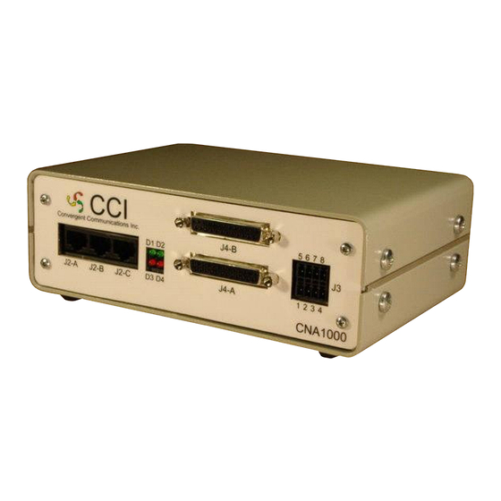
The IP address for access to communications interfaces on the CNA1000 whether it is the CNA1000 may be hard-coded by the user or it can be configured shelf or DIN rail mounted. Three RJ45 jacks are provided for the to search for a remote DHCP server. - Page 5 Phoenix Part Number 1952283 Optically Isolated OUTPUTS J3, pins 1 through 4 4-position Phoenix FMC 1,6/ 4-ST3,5 Phoenix Part Number 1952283 4) LED Displays D1 through D4 Assignments are application dependent Figure-2a: CNA1000 Physical Interfaces Figure-2b: CNA1000 Physical Interfaces Front Panel Rear Panel...
- Page 6 Connectors and Pin Assignments Connectors and Pin Assignments Synchronous Serial Communications Asynchronous Serial Communications RS232 synchronous serial communications is available on the front RS232 asynchronous serial communications is available on the panel serial ports J4-A and J4-B on DB-25 female connectors. The pin front panel through serial ports J2-A, J2-B, and J2-C on the assignments for DB-25 female connectors J4-A and J4-B are shown in provided RJ-45 jacks.
- Page 7 Pin 1 Pin 8 DC Input Supply The CNA1000 operates on 9 to 18 VDC input and is DC isolated to a minimum of 2000 VRMS. Figure-5: Ethernet Network Connector J-5 The pin assignment for DC supply input is shown in Figure-7 below.
-
Page 8: Default Configuration Parameters
Default Communications Settings Front panel LED indicators provide visual indications of activity during the The CNA1000 is designed to support custom protocol conversion across power up and DHCP processes. Under default conditions, during the boot the provided communications network interfaces. The individual serial sequence, all front panel LED indicators are illuminated. -
Page 9: Supported Protocol Platforms
Supported Protocol Platforms Supported Protocol Platforms Application Dependent Configuration Parameters Application Dependent Configuration Parameters (cont.) During programming, the provided CNACONFIG utility allows the user CNA1004 to select from one of the available pre-assigned application Application: Base Station to IP Network Adapter configurations. - Page 10 Supported Protocol Platforms Supported Protocol Platforms Application Dependent Configuration Parameters (cont.) Application Dependent Configuration Parameters (cont.) CNA1006 CNA1009 Application: Monitoring HP-1 Code Unit Communications and Application: Connects ATCS (serial HDLC) field devices to an ATCS HDP Code Server Communications messaging; office system via UDP Communications Port Assignments: Communications Port Assignments:...
- Page 11 Supported Protocol Platforms Supported Protocol Platforms Application Dependent Configuration Parameters (cont.) Application Dependent Configuration Parameters (cont.) CNA1014 CNA1017 Application: Connects an ARES radio to a GTC serial controller Application: Connects a Genisys field device via an ARES radio to an Communications Port Assignments: ATCS office J2-B = virtual terminal 1...
- Page 12 Default = 9600 baud; 8/N/1 ENET-LAN = Configuration and debug only Additional signaling and communications protocols are scheduled for release in the near future. Please refer to the CCI website ww.ccinet.us to retrieve a current list of supported protocols. The...
- Page 13 Upon startup of the CNACONFIG utility, the user is presented the The above function areas on the CNACONFIG programming screen are opportunity to enter an IP address of a CNA1000 unit that has been identified in Figure-11. configured and placed into service. Alternatively, the user may Cancel or exit from the startup window and proceed directly to the CNA Configuration Utility Main screen.
- Page 14 File Menu Command Bar Functions Under the File menu command bar the available options are: Target IP… to enter an IP address to select an individual CNA1000 unit; Load… to open up a previously saved CNA1000 configuration file; Save… the configuration file currently being edited;...
- Page 15 CNACONFIG CNACONFIG Platform Menu Command Bar Functions (cont.) Option Menu Command Bar Functions CNA1016… ATCS wireline to ATCS /160MHz converter The Program Options menu allows the user to enable certain warnings CNA1017… Genisys to ATCS / 160MHz converter and confirmation messages to be displayed during the programming CNA1018…...
- Page 16 CNACONFIG CNACONFIG Online Menu Command Bar Functions Online Menu Command Bar Functions (cont.) Search for CNAs… Under the Online menu command bar the user can connect to a CNA and examine its optically isolated ports. Enter a specific IP address or IP subnet in the box at the bottom of the window and click the Search button.
- Page 17 The Password field configures the TELNET password used to login to the CNA1000 ID Block Common Parameters CNA1000. This field is not available on CNA1000 platforms that do not support TELNET access. CNA id: and the Version fields are for information only and display the selected protocol platform and the version of hardware platform for the build of software.
- Page 18 Configuration Parameters” section above to determine which physical Codeline entry field allows the user to assign a four digit codeline CNA1000 ports are used by a given CNA platform for virtual terminal 1 and number. The codeline number will typically match that of the assigned virtual terminal 2.
- Page 19 CNACONFIG CNACONFIG CNA1001 Platform Selection (cont.) CNA1001 Platform Selection (cont.) HP-1 Addressing Figure-15: CNA1001 Platform Selection CNA1003 Platform Selection Genisys Addressing Application: Genisys over IP LAN/WAN Networks The CNA1003 application was specifically designed to support the connection of a railroad field code unit enabled with the serial US&S® Genisys asynchronous communications protocol to a packet data, IP based communications network.
- Page 20 CNACONFIG CNACONFIG CNA1003 Platform Selection (cont.) CNA1003 Platform Selection (cont.) CNA1003 Communications Port Assignments • J2-C Genisys Serial Communications Baud Rate: User Configurable; 1200, 2400, 4800, or 9600 Default = 9600 baud; 8/N/1 • J5 LAN connection to Genisys Office; Remote Configuration and Diagnostics;...
- Page 21 Application: ATCS / ARES / GTC RF Network Interface to an IP LAN/WAN Networks When the CNA1004 protocol platform is selected, the CNA1000 assembly is preset to support the network interface of ATCS / ARES / GTC data base station radio infrastructures to a LAN/WAN IP packet data network.
- Page 22 CNACONFIG CNACONFIG CNA1004 Platform Selection (cont.) CNA1004 Platform Selection (cont.) The Base Type drop down menu allows the user to choose the base station type to match the data radio infrastructure. The selections presently supported are ARES, ATCS, or a Ground Terminal Controller (GTC) for ARES systems.
- Page 23 Application: Protocol Conversion Genisys to WSA S2 The S2 configuration parameters are as follows. When the CNA1005 protocol platform is selected, the CNA1000 Base Address: the polling address of the attached S2 field code unit assembly is preset to support WSA S2 to Genisys protocol conversion.
- Page 24 The User monitors the communications activity from the two attached code units on their laptop through Ethernet LAN connection J-5. Since it is an IP connection to the CNA1000, the User may monitor the activity either locally or remotely. Infrastructures •...
- Page 25 “mon0” and is presented in red font. The data from the HP1 code unit attached to port J4-B is labeled “mon1”and is presented in blue font. Local CNA1000 commands are logged in black font. Figure-19: CNA1006 Platform Selection Figure-20: CNACONFIG log screen...
- Page 26 C000-26005-0001 DATE ORIGINAL SCALE 12-DEC-08 None NOTES: 1) HP-1MON application for use with CNA1000 Hardware and loaded with CNA1006 version software application LATEST REVISION JOB NO. CHECKED DRAWN Convergent Communications, Inc. 2) CNA1006v2.0.0 software of higher supports both the HP-1MON and HDP_MON applications concurrently...
- Page 27 C000-26004-0001 DATE ORIGINAL SCALE 12-DEC-08 None NOTES: 1) HP-1MON Cable Diagrams for use with CNA1000 Hardware and loaded with CNA1006 version software application LATEST REVISION JOB NO. CHECKED DRAWN Convergent Communications, Inc. 2) CNA1006v2.0.0 software or higher supports both the HP-1MON and HDP_MON applications concurrently...
- Page 28 C000-26008-0001 DATE ORIGINAL SCALE 31-MAR-09 None NOTES: 1) HDP_MON application for use with the CNA1000 Hardware loaded with CNA1006v2.0.0 software application or higher LATEST REVISION JOB NO. CHECKED DRAWN Convergent Communications, Inc. 2) CNA1006v2.0.0 supports both the HP1_MON and HDP_MON applications concurrently...
- Page 29 C000-26009-0001 DATE ORIGINAL SCALE 31-MAR-09 None NOTES: 1) HDP_MON Cable Diagrams for use with CNA1000 Hardware loaded with CNA1006v2.0.0 software application or higher LATEST REVISION JOB NO. CHECKED DRAWN Convergent Communications, Inc. 2) CNA1006v2.0.0 supports both the HP1_MON and HDP_MON applications concurrently...
- Page 30 CNACONFIG CNACONFIG CNA1006 Platform Selection (cont.) CNA1006 Platform Selection (cont.) The typical procedure for using the HP1-MON or the HDP_MON application would be as follows: 1. Connect all cabling as applicable for either application as shown in the previous drawings. 2.
- Page 31 CNACONFIG CNACONFIG CNA1007 Platform Selection CNA1007 Platform Selection (cont.) Application: Connects Genisys field device to an ATCS office system via Route Request IP (RouteReq IP) is the IP address of the primary office UDP. communications gateway (OCG) device to communicate with. RouteReq IP2 is the IP address of an alternate OCG to communicate with if the CNA1007 Communications Port Assignments connection is lost with the primary OCG.
- Page 32 CNACONFIG CNACONFIG CNA1007 Platform Selection (cont.) CNA1008 Platform Selection When the Enable HMAC box is checked, the ATCS communication is Application: Connects ATCS (serial HDLC) field devices to an MCP via validated by adding an HMAC. The HMAC key is encrypted using the RC2 Key.
- Page 33 CNACONFIG CNACONFIG CNA1008 Platform Selection (cont.) CNA1009 Platform Selection (cont.) • J4-B ATCS HDLC serial Sync Clocks: User Configurable; External / Internal 1200, 2400, 4800, 9600, 19200, 38400, 57600, or 115200 • J5 LAN connection for ATCS over UDP; Remote Configuration and Diagnostics;...
- Page 34 CNACONFIG CNACONFIG CNA1009 Platform Selection (cont.) CNA1009 Platform Selection (cont.) The Debug byte in the ATCS section turns on and off diagnostic information from the ATCS stack, values are 0 for Off, 1 for Normal and 2 for High, with a default of 0. Route Request IP (RouteReq IP) is the IP address of the primary office communications gateway (OCG) device to communicate with.
- Page 35 CNACONFIG CNACONFIG CNA1012 Platform Selection CNA1012 Platform Selection (cont.) Application: MCS-1 to ATCS IP converter Route Request IP (RouteReq IP) is the IP address of the primary office communications gateway (OCG) device to communicate with. RouteReq CNA1012 Communications Port Assignments IP2 is the IP address of an alternate OCG to communicate with if the •...
- Page 36 CNACONFIG CNACONFIG CNA1012 Platform Selection (cont.) CNA1013 Platform Selection Application: Dark Territory switch monitor MK-1 which connects RailFly clusters to the ITC network CNA1013 Communications Port Assignments • J2-B GPS serial NMEA data Baud Rate: User Configurable; 1200, 2400, 4800, or 9600 Default = 9600 baud;...
- Page 37 Class D IP and Port are the IP Address and Port of the Class D server that the CNA1013 will try to connect to, which have default values of 4. Click the Get Status button on the CCI RailFly sensor monitor 192.168.7.199 and 8081 respectively.
- Page 38 CNACONFIG CNACONFIG CNA1014 Platform Selection CNA1013 Platform Selection (cont.) Application: Connects an ARES radio to a GTC serial controller CNA1014 Communications Port Assignments • J2-B Virtual terminal 1 • J2-C ARES async serial data (RSSI information) Baud Rate: User Configurable; 1200, 2400, 4800, 9600, 19200, 38400, 57600, or 115200 Default = 9600 baud;...
- Page 39 CNACONFIG CNACONFIG CNA1014 Platform Selection (cont.) CNA1015 Platform Selection (cont.) Configurable Parameters The Peer section contains parameters for communication with the Object Controller. The Data TCP port is the TCP/IP port for data Tx/Rx with Object Controller, which has a default of 4001. The HMAC TCP port is the TCP/IP port for HMAC key exchange with Object Controller, which has a default value of 4003.
- Page 40 CNACONFIG CNACONFIG CNA1016 Platform Selection CNA1017 Platform Selection Application: Connects an ATCS (serial HDLC) field device via an ARES Application: Connects a Genisys field device via an ARES radio to an radio to an ATCS office ATCS office CNA1016 Communications Port Assignments CNA1017 Communications Port Assignments •...
- Page 41 CNACONFIG CNACONFIG CNA1017 Platform Selection (cont.) CNA1018 Platform Selection (cont.) • J4-A Virtual terminal 2 The CNA and Office are the ATCS addresses of the base address for the • J5 attached Genisys devices and the address of the LTC in the office LAN connection for ATCS over UDP;...
- Page 42 CNACONFIG CNACONFIG CNA1020 Platform Selection CNA1018 Platform Selection (cont.) Application: BNSF Tower Light Monitor. The Debug byte in the ATCS section turns on and off diagnostic information from the ATCS stack, values are 0 for Off, 1 for Normal and 2 CNA1020 Communications Port Assignments •...
- Page 43 CNACONFIG CNACONFIG CNA1022 Platform Selection CNA1020 Platform Selection (cont.) The NTP IP Address and NTP IP address 2 are the Network Time Application: BNSF Tower Light Monitor. Protocol Primary and Backup Server IP Addresses used to synchronize the CNA1020 clock using Simple Network Time Protocol. If configured, CNA1022 Communications Port Assignments the CNA1020 will send NTP version 3 time request messages to the •...
- Page 44 CNACONFIG CNACONFIG CNA1022 Platform Selection (cont.) Figure-33: CNA1022 Platform Screen...
-
Page 45: Specifications
Specifications Contacts Convergent Communications Incorporated General • Microprocessor: Rabbit 3000 @ 44.2 MHz • SRAM: 512K pgm + 512K data Corporate • Flash Memory: 512K + 4 Mbyte serial P.O. Box 1052 • Clock: Real Time Clock Paonia. CO 81428 Telephone: (909) 972-6942 Network Interface •...
Need help?
Do you have a question about the CNA1000 and is the answer not in the manual?
Questions and answers