Table of Contents
Advertisement
Quick Links
Advertisement
Table of Contents

Summary of Contents for IMG BRASIL BIMG METVISA FTE.150
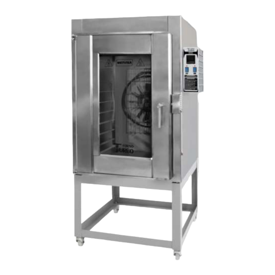
- Page 2 CONGRATULATIONS, You have just purchased a IMG-BRASIL equipment, product of the highest quality, safety and efficiency. Founded in 1989, IMG-BRASIL is a respected company as one of the best and most complete companies in the field of gastronomy equipment manufacturing. Constant innovation and improvement of its products, using top-of-the-line raw materials, ensure superior products consumed in Brazil and in more than 25 countries worldwide.
-
Page 3: Table Of Contents
Explosion Design ..........................30 Replacement parts ........................... 34 ATTENTION! The characteristics, pictures and figures presented in this manual should be considered for information. IMG BRASIL reserves the right to make such modifications as may be deemed necessary without prior notice. -
Page 4: Safety Information
1. Safety Information 1.1 General Warnings • Cautions / precautions must be observed when installing, using, maintaining and discontinuing use of this equipment; • Before carrying out any operation (assembly, use (use), maintenance and reuse after prolonged use of the equipment), read the manual carefully; •... -
Page 5: Mechanical Safety
1.2 Mechanical Safety • Before operating the equipment, make sure that the gas installation is free of leaks, if the pressure of the hydraulic system is within the permitted levels (see pressure information in item 3.2 Hydraulic Installation) and if the door is locked until the handle stroke limit. •... -
Page 6: Technical Features
• Lay the equipment on a firm, dry, level surface; • Never carry out any maintenance, adjustment or disassembly of the equipment connected to it. For such procedures, make sure that it is turned off by removing the plug from the electrical outlet; •... -
Page 7: Technical Data
Note: For exploded design with spare parts list, see the attachments. 2.2 Technical Data Standard Measures Electrical Rated Energy Capacity Roasting Dimension Voltage for Operation Weight Model Cable Current Consumption (bread) pans Roasting Length.xHt.xWidth (approx.) Section (kW/h) (unit) pans (mm) (mm) * (kg) FTE150220M60... -
Page 8: Supply And Disposal Of Equipment Packagin
ATTENTION! Features like: model, serial number and voltage of the equipment are provided on the label (figure below). Before installation, check that the power supply voltage of the appliance corresponds to that of the mains. 2.3 Supply and Disposal of Equipment Packagin The equipment is packed with wood or cardboard to ensure its perfect integrity during transport and is accompanied by the following documents: •... - Page 9 Follow the guidelines below to assemble the stand:...
- Page 10 With the stand mounted, position the top rack of the oven (FTG.150) on top of the stand, noting that the swivel casters are positioned in the front of the oven. Mount with washers, bolts and nuts. Make sure all bolts are tight. To ensure correct operation and safety, the equipment should be positioned in a sufficiently wide area, with a well-leveled, dry and stable floor, away from sources of heat and humidity and where there is no heavy traffic.
-
Page 11: Hydraulic Installation
It is recommended to install a hood or extractor above the oven to collect the vapors, avoiding that they spread in the environment. IMPORTANT To install the hood follow the manufacturer's instructions as this item does not accompany the equipment. ATTENTION! The installation and the place where the appliance is to be disposed of must comply with the rules of risk prevention and safety at work (Regulatory standard NR-12 for Brazil or according... - Page 12 The equipment is supplied with a solenoid water valve for hose coupling or for fitting a 3/8 "water supply hose (hose and pipes not supplied with the equipment) located on the back of the control panel housing. The hose that will be used to connect to the water supply must comply with IEC 61770. When installing the hose, ensure that the pressure reducing ring (attached to the equipment) is properly sealed to prevent leakage.
-
Page 13: Electrical Connection
In case the excess steam turns into water inside the oven (chamber), it may be drained through the water outlet pipe located between the bottom of the chamber and the oven burners. It is advisable to install a point to drain this water, avoiding that the floor is wet and slippery and can cause accidents. - Page 14 The Electric Terminal identified in the figure below is an additional rotection for the grounding that is provided in the mains. It must be connected to a grounding terminal bar, regardless of the connection to the mains, and ther products that have accessible metallic parts. And which are stationary, must also be connected to this bus as well as the service bench itself, in case it is of metallic material .
-
Page 15: Safety Procedures And User Instruction
IMPORTANT The manufacturer is not responsible for possible direct or indirect damages caused by non- compliance with said standards and other instructions presented in this manual. 3.4 Safety Procedures and User Instruction The professional who sells the equipment must instruct the user on its correct operation and must deliver this instruction manual. -
Page 16: Commands
4.2 Commands The equipment consists of controller, power button and on / off switch light. The controller and buttons are located on the front panel of the control panel. See description of each command below: • Power Button - used to turn the equipment on and off. In position "1" turns on, in position "0" turns off. - Page 17 1 - Display that indicates the temperature present in the temperature sensor or the programmed temperature; 2 - Display indicating elapsed time or programmed time; Led timer indicator; Timer key: activates or cancels the timer; Steam output indicator light on; Single steam time trigger button.
-
Page 18: Operating Procedures
To deactivate the cyclic steam function, press the key The controller has a system that checks for possible faults in the temperature sensor. This fault can be seen on the display. Check the description of the failure: Display Descrição Some corrupted configuration parameters were detected and for safety all of them were restored to their factory value. - Page 19 ATTENTION! The Oven leaves the factory with temperature programmed at 200° C and cooking time 60 minutes. Due to this programming, as soon as the on / off button is pressed the oven starts the heating and rotation of the turbine. To reprogram the cooking temperature and time, follow the instructions below.
-
Page 20: Cleaning And Maintenance
14. After the work is finished, turn off the machine by pressing the power button in the "0" (off) position; 15. Before cleaning your machine, wait until the inside of the oven reaches room temperature. • Temperatures: Temperature Table and Cooking Time Product Temperature (°C) Time (min.) -
Page 21: Maintenance And Behavior In Case Of Breakdowns
IMPORTANT This equipment not intended to be fully immersed in water for cleaning. Follow the instructions below to find out how to take special care of the equipment. Carry out the cleaning on the inside, outside and the rubber of the oven as many times as possible to prevent food residues from drying out and stick to the parts. -
Page 22: Prolonged Interruption In Use Of Equipment
When you experience any malfunction or non-compliance, refer your equipment to the nearest service center. See technical assistance on our website: www.metvisa.com.br 5.3 Prolonged Interruption in Use of Equipment When leaving the appliance unattended for an extended period of time, unplug it from the mains, keep the oven door open, and perform a thorough cleaning, including the various accessories. -
Page 23: Appliance Life And Components
Voltage different from mains Send the equipment to the nearest authorized service voltage. station or contact the factory. Miscellaneous electrical problems. Equipment with smell of Burned food Very high temperature and or baking time. burning or smoke. For the first use of the equipment it is necessary to Failure to cure the paint inside cure the paint inside the oven (chamber). -
Page 24: Annexes
8. ANNEXES Electrical Schematic FTE.150 - Voltage 220 V - Single Phase Connection NOTE: FTE.150 oven uses nly one Door Light. -
Page 25: Electrical Schematic Fte.150 - Voltage 220 V - Three Phase Connection
Electrical Schematic FTE.150 - Voltage 220 V - Three Phase Connection NOTE: FTE.150 oven uses only one Door Light. -
Page 26: Electrical Schematic Fte.300 - Voltage 220 V - Three Phase Connection
Electrical Schematic FTE.300 - Voltage 220 V - Three Phase Connection... -
Page 27: Electrical Schematic Fte.150 - Voltage 380 V - Three Phase Connection
Electrical Schematic FTE.150 - Voltage 380 V - Three Phase Connection NOTE: FTE.150 oven uses only one Door Light. -
Page 28: Electrical Schematic Fte.300 - Voltage 380 V - Three Phase Connection
Electrical Schematic FTE.300 - Voltage 380 V - Three Phase Connection... -
Page 29: Explosion Design
Explosion Design... - Page 30 Explosion Design...
- Page 31 Explosion Design...
- Page 32 Explosion Design...
-
Page 33: Replacement Parts
Replacement parts Position Code Description Qty. Model Application TUC027 Water Outlet Tube FTE.150/ T ARL002 Flat Washer FTE.300/ T FCH015 Oven Door Lock PTC088 Micro-Key Protection - FTE.150 FTE.150/ T PTC078 Micro-Key Protection - FTE.300 FTE.300/ T FTE.150 PRS003 Hexagonal Screw FTE.300 FTE.150T PRS023... - Page 34 Replacement parts Position Code Description Qty. Model Application FTE.150 TAP113 Painted Electric Box Lid FTE.300 13.1 FTE.150T TAP143 Stainless Steel Electrical Box Lid FTE.300T FTE.150 PRA005 Locking Screw Hex FTE.300 13.2 FTE.150T PRA014 Stainless Steel Locking Screw. Hex FTE.300T 13.3 PCC008 Screw Phillips FTE.150/T 220 MF...
- Page 35 Replacement parts Position Code Description Qty. Model Application GRA001 Fan Protection Grid - FTE.150 FTE.150 GRA005 Stainless Steel Fan Protection Grid - FTE.150T FTE.150T GRA003 Fan Protection Grid - FTE.300 FTE.300 GRA006 Stainless Steel Fan Protection Grid - FTEI.300 FTE.300T TUC024 Water Fan Tube TRB002...
- Page 36 Replacement parts Position Code Description Qty. Model Application GAB113 Left Side Oven Structure - FTE.150 FTE.150 GAB140 Left Side Oven Structure - FTE.150T FTE.150T GAB162 Left Side Oven Structure - FTE.300 FTE.300 GAB135 Left Side Oven Structure - FTE.300T FTE.300T ETR070 Complete Oven Structure - FTE.150 FTE.150...
- Page 37 Replacement parts Position Code Description Qty. Model Application SBT432 Left Tray Support Galvanized - FTE.150 FTE.150 SBT284 Left Tray Support Stainless Steel - FTE.150/T FTE.150/T SBT280 Left Tray Support Stainless Steel - FTE.300 FTE.300/ T TUC026 Water Inner Tube - FTE.150 FTE.150/T TUC023 Water Inner Tube - FTE.300...
- Page 38 Notes...
- Page 40 IMG BRASIL Gastronomy Machinery Industry Ltda. CNPJ 11.193.347/0001-14 - CREA 131726-3 Road. Antônio Heil - KM 23 Nº 5825 - Neighborhood: Limoeiro ZIP CODE 88352-502 - Brusque - SC - Brazil Phone/fax. +55 47 3251-5555 - Web Site: www.metvisa.com.br Mail: sac@metvisa.com.br - export@metvisa.com.br...