Table of Contents
Advertisement
Advertisement
Table of Contents

Summary of Contents for Furness controls FCO432
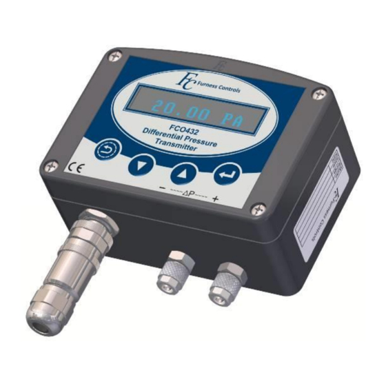
- Page 1 FCO432 Differential Pressure Transmitter Users Guide Please read carefully before using. Manufactured by: Furness Controls Limited Beeching Road, Bexhill, East Sussex, TN39 3LG, England. Telephone +44(0) 1424 819980 Email: Sales@furness-controls.com Web Site: http://www.furness-controls.com...
- Page 2 Page 2 FCO432 Users Guide Issue 1...
-
Page 3: Table Of Contents
M12 (4-pole) Electrical Connection ....................32 DIN Electrical Connection........................32 DIN with External Zero ........................33 Specification ............................34 Dimension Drawings ........................... 35 Basic Instrument ..........................35 Pipe Mounting Kit ..........................35 Wall Mounting Kit ..........................36 FCO432 Users Guide Issue 1 Page 3... -
Page 4: Revision Record
Revision Record Issue Date Summary of changes 26-11-18 First release Page 4 FCO432 Users Guide Issue 1... -
Page 5: Safety Notes And Recommendations
3. The air supply must be turned off before carrying out any work on the pneumatic system. 4. The air supply must not exceed that specified on the instrument or in the Test Certificate. 5. If in doubt about any aspect of safety with the equipment then contact Furness Controls BEFORE proceeding. -
Page 6: Introduction
The output can be scaled as a linear or rooted function to facilitate the use of Pitot Static Tubes or other primary flow elements. The FCO432 is suitable for industrial applications of control, measurement and monitoring. -
Page 7: Installation
Installation Mounting The recommended mounting position of the FCO432 is with the pressure entry ports facing directly downwards. This helps prevent the ingress of dust and liquid. Due to the sensitivity of lower range instruments, they should not be mounted in areas where they will be subjected to high vibration as this could cause spurious readings. -
Page 8: Electrical
Electrical The FCO432 is fitted with a M12 connector as standard. See the “Alternative electrical connections” section at the end of this user guide for non-standard connector information. M12 (5-Pole) Electrical Connection Connector type: 5-Pole M12 female, Code A, shielded, straight, field installable connector with screw terminals and a PG9 cable gland (suitable for cable Ø4 to Ø8mmOD). - Page 9 Connector wiring Assembly Note Housing alignment tabs must be fitted into the plastic locating slots and not the electrical terminals FCO432 Users Guide Issue 1 Page 9...
- Page 10 Connector type: 5-Pole M12 female, Code B, straight, field installable connector with screw terminals and a PG9 cable gland (suitable for cable Ø4 to Ø8mmOD). The FCO432 can incorporate a pair of relays for triggering auxiliary equipment such as alarms. Note the relays are supplied from the +24V on the power connector.
-
Page 11: Commissioning
Press & hold for 1 second NOTE: if the auto zero valve is fitted, pressing either the zero button or the remote zero will force an auto zero cycle. The instrument is now ready for operation. FCO432 Users Guide Issue 1 Page 11... -
Page 12: Fcs541 - 400 Utility Software
Installation USB-B Connection The FCO432 is fitted with a Micro USB-B connector on the main circuit board and can be fitted with an optional external USB-B port. USB drivers and support tools are available on the Furness Controls product CD (\Drivers\USB drivers) or may be downloaded from http://www.furness-controls.com/filelist. - Page 13 The write settings tab allows the settings to be saved to text (.txt) file and formatted with each heading and the setting that has been applied to it. The Write settings button will save all the Transmitter settings under the headings from the 400 Series firmware menu. FCO432 Users Guide Issue 1 Page 13...
-
Page 14: Instrument Settings
├ Purge ├ Test ├ Comms │ ├ BAUD │ └ Flash ├ User LIN │ ├ Point 1…5 │ └ % Adj 1…5 ├ F. Level ├ Version ├ Serial └ Unit ID Page 14 FCO432 Users Guide Issue 1... -
Page 15: Menu Navigation
Dampens the transducer response to reduce fluctuations when measuring turbulent flows. Options: 0.0 to 60.0 seconds Filter considerations: There are three factors that affect the response time of the output signal for a step change in input pressure. FCO432 Users Guide Issue 1 Page 15... - Page 16 1Bar to 10Bar instruments Unit Description Unit Description Pascal Kilo Pascal Kilo Pascal Millibar Millibar Millimetre H2O gauge P.S.I.G. Inches H2O gauge Inches H2O gauge Millimetre Hg Millimetre Hg Inches Hg Inches Hg Page 16 FCO432 Users Guide Issue 1...
- Page 17 For instance, to display in mA set the value to 20.00. For %, set this value to 100. Options: Any numeric value shown on the display FCO432 Users Guide Issue 1 Page 17...
- Page 18 DISP RL 1/2 (Relay 1 & 2 Display Alarm) Purpose: Selects the condition that causes a visual alarm to be displayed momentarily and repeated at regular intervals on the FCO432’s display. Options: NONE, RESET, SET NONE No Alarm message displayed for relay...
- Page 19 Options: OFF, ON OFF Manual auto-zeroing can be performed ON Manual auto-zeroing is prohibited. FCO432 Users Guide Issue 1 Page 19...
- Page 20 This feature gives users the ability to define 5 linearity correction points (stored as %span), which can be used to modify the FCO432’s linearity. This can be used to remove the non-linearity of an attached sensor such as a flow element.
- Page 21 -0.4Vdc 10.4Vdc 1Vdc (4-wire isolated) -1.02Vdc 1.02Vdc -1.04Vdc 1.04Vdc 2 Vdc (4-wire isolated) -2.04Vdc 2.04Vdc -2.08Vdc 2.08Vdc 5 Vdc (4-wire isolated) -5.1Vdc 5.1Vdc -5.2Vdc 5.2Vdc 10 Vdc (4-wire isolated) -10.2Vdc 10.2Vdc -10.4Vdc 10.4Vdc FCO432 Users Guide Issue 1 Page 21...
-
Page 22: Troubleshooting
1000. Pressing twice will reset the to alter the first digit. PIN Number lost Contact your Furness Controls representative for advice on how to restore the pin number to its default value. Page 22 FCO432 Users Guide Issue 1... -
Page 23: Error Messages
Error Messages The FCO432 displays an error number, followed by a description of the error. The description is scrolled across the display after a short delay. Error 0 EEPROM calibration data error Calibration data stored in the EEPROM may have become corrupted. -
Page 24: Calibration
Calibration Furness Controls recommend that all pressure transmitters and flow devices are recalibrated annually. For critical applications, it is advisable to check the calibration more frequently. All calibration adjustments of 400 series pressure transmitters are performed through a PC using the FCS541 Utility software/cable or using the optional keypad. -
Page 25: Recalibration Using The Fcs541 Utility
The Mid button sets the output to the mid-point value (e.g. 12mA). The Maximum button sets the output to the maximum value (e.g. 20mA). The Reset button immediately cancels test mode and returns the output to normal. FCO432 Users Guide Issue 1 Page 25... -
Page 26: Calculations
Where: V Velocity in m/s P Differential pressure from the Pitot tube in Pascal's K Furness Controls Pitot tube correction factor (FCO65 = 1) T Static temperature in Kelvin (°C + 273.14) P Absolute static pressure at the Pitot tube in Pascal's ... - Page 27 /s (flow at standard temperature and pressure). Density of the gas at standard conditions in kg/m Density can be calculated by multiplying the relative density by the density of air at standard conditions (air = 1.2kg/m @101325Pa, 20°C). FCO432 Users Guide Issue 1 Page 27...
-
Page 28: Laminar Flow Element Calculation
= 385. This is a correction factor to approximate tabulated data on viscosity changes with temperature. If a measure of mass flow rate is required, refer to the mass flow calculation at the end of the Pitot Tube Calculation section. Page 28 FCO432 Users Guide Issue 1... -
Page 29: Applications
The scale can be any pressure within the maximum range of the FCO432. Example: Using the FCO432 to measure the draft suction in a flue stack. The normal pressure is -5mb but the FCO432 needs to be able to indicate pressures from +1mb to -16mb. A Model 4 FCO432 is selected which has a maximum differential pressure range of 25mb. -
Page 30: Using A Laminar Flow Element
Therefore, a Model 2 FCO432 is selected which has a maximum differential pressure range of 150Pa. The FCO432 needs configuring to measure 0 to 44.4Pa with a display of 0 to 16 l/m. Set the Display mode to Custom ... -
Page 31: Using A Pitot Static Tube
P = 19.44 Pa Therefore, a Model 1 FCO432 is selected which has a maximum differential pressure range of 50Pa. The desired scaling is 0 to 19.44Pa (4 to 20mA) with a display of 0 to 8 m Referring to the Menu Details section: ... -
Page 32: Alternative Electrical Connections
Isolated 4 to 20mA 4 to 20mA Voltage Output Output Output Vout- +24Vdc +24Vdc Vout+ 0Vdc 0Vdc See rating label for power supply requirements and configuration The diagrams below show typical wiring configurations: Page 32 FCO432 Users Guide Issue 1... -
Page 33: Din With External Zero
1.5 seconds while the pneumatic ports are isolated from the process ports. The diagram below shows a typical wiring configuration: 4 to 20mA Output Ext Zero See rating label for power supply requirements and configuration FCO432 Users Guide Issue 1 Page 33... -
Page 34: Specification
IP54 rated ABS enclosure Dimensions W120mm x H85mm x D58mm Materials in Contact With Copper, brass, nickel, mica & PVC Media Media Compatibility Air and non-corrosive gases max 95% humidity non-condensing Weight 0.5kg Page 34 FCO432 Users Guide Issue 1... -
Page 35: Dimension Drawings
Dimension Drawings Basic Instrument Pipe Mounting Kit FCO432 Users Guide Issue 1 Page 35... -
Page 36: Wall Mounting Kit
Wall Mounting Kit Page 36 FCO432 Users Guide Issue 1...
Need help?
Do you have a question about the FCO432 and is the answer not in the manual?
Questions and answers