Table of Contents
Advertisement
Quick Links
Dear user:
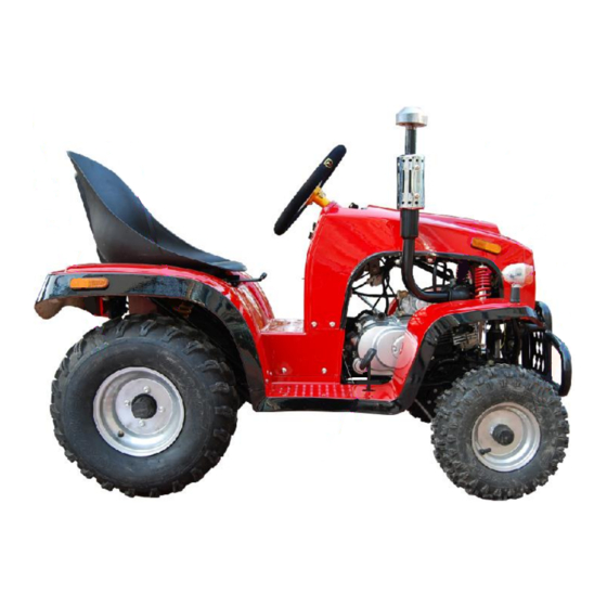
Thank you for your selection of our Nitro Motors 110cc Tractor
Our Nitro Motors 110cc Tractor car designed with the latest technology is suitable for recreation and competition. It is equipped with single-cylinder 4-stroke
air-cooled engine and convenient electric start. It is fixed with front and rear shock absorber to improve comfort during driving. Its front wheel is fixed with drum
type brake and its rear wheel with top quality hydraulic disk type brake to render safe and reliable braking.
The Nitro Motors 110cc Tractor is deluxe, artistic, dynamic, and attractive.
Most of the frame is of steel tube structure. During driving, please take care of safety.
We warmly welcome your opinions and suggestion on design and workmanship.
This instruction outlines the basic structure, safe driving, operation, maintenance and main technical parameters of Nitro Motors 110cc Tractor and should be
carefully read. In order to make the car durable and prolong its service life, please carefully follow the instruction.
The Nitro Motors 110cc Tractor will be subjected to continuous improvement without notice.
· For the Nitro Motors 110cc Tractor merely one driver and load up to 100kg are allowed and over-load would
make the car out of control.
· Any one below 16-age is not allowed to drive the car.
· During driving, please wear safety cap and clothes and other protective goods.
· Any one after drinking or taking drug shall not drive the car.
· The Nitro Motors 110cc Tractor may be fixed with 50cc 、90cc and 110cc engine. Please carefully read the
instruction.
· Not drive the car in highway.
· Failure to follow the instruction would result in accident or damage of car or its components.
· Not drive the car before understanding its performance or let anyone drive the car who is unable to drive it.
· The instruction is an integral part of the car and shall be accompanied with the car when it is transferred to other person.
· Copyright reserved. Any part of the instruction shall not be duplicated without our written consent.
Preface
Note
Important
1
Advertisement
Table of Contents

Subscribe to Our Youtube Channel
Summary of Contents for Nitro motors 110cc
- Page 1 Thank you for your selection of our Nitro Motors 110cc Tractor Our Nitro Motors 110cc Tractor car designed with the latest technology is suitable for recreation and competition. It is equipped with single-cylinder 4-stroke air-cooled engine and convenient electric start. It is fixed with front and rear shock absorber to improve comfort during driving. Its front wheel is fixed with drum type brake and its rear wheel with top quality hydraulic disk type brake to render safe and reliable braking.
-
Page 2: Table Of Contents
2.2.5 Fuel and oil tank cover Maintenance schedule Allocation notes exchangeable engines (50 、 2.2.6 Fuel switch 90CC and 110CC) 2.2.7 Selection of lubricating oil Accompanied tools 2.2.8 Tire Main technical parameters Guide to operation Schematic electric diagram Start of engine... -
Page 3: Safe Driving Of Car
1. Safe driving of car Important During driving, please obey state regulations on traffic safety and traffic management. The car shall be driven only after inspection. The car is merely allowed to drive in non-traffic field and shall not be driven in highway. 1.1 Rules of safe driving ·... - Page 4 · Please fill the number of engine and car identification code in the following spaces for reference. Number of engine: □□□□□□□□□□□□□□□□□ Car identification code Notes: Number of engine: Stamped on plane of left side of the engine (shown in Fig. 1). Frame identification code: Stamped on right front side of the frame (shown in Fig.
-
Page 5: Position Of Main Components
2.2 Positin of main components: -Fig. 3-... - Page 6 -Fig. 4-...
- Page 7 Fig. 5- -Fig. 6-...
- Page 8 List of main parts: Designation Designation Designation Front wheel Parking rocker arm Chain guard Front bumper rear shock absorber Rear brake Front turn indicator carburetor Rear braking disk Left front shock Right front shock Exhaust tube absorber absorber Air filter accelerator pedal Rear right turn indicator Oil tank cover...
-
Page 9: Position And Operation Of Instrument
2.2.1 Position and operation of instrument indicator lamps and electric control switch Functional keys: 1. Display of oil volume 2. Reverse indicator lamp 3. Neutral indicator lamp 4. Transmission-1 indicator lamp 5. Transmission-2 indicator lamp 6. Transmission-3 indicator lamp 7. Start switch 8. -
Page 10: Ignition Switch
2.2.2 Ignition switch The position of ignition switch is shown in Fig. 7-7. OFF: Denoting that the circuit is cut off, the engine at dead state and the key can be withdrawn. (· ): Denoting that the circuit is in on-state, the engine may be started and the key is impossible to withdraw. 2.2.3 Indicator lamp The positions of indicator lamps are shown in Fig. -
Page 11: Fuel Switch
After fueling, the oil pipeline shall be checked for leakage and the oil tank cover shall be tightly screwed, otherwise, gasoline outwards leaking from oil tank through the cover would result in safety hidden trouble. 2.2.6 Fuel switch Fuel switch is fixed at middle right of bottom of oil tank and is set on state (Shown in Fig.8). Notes to position of handle of fuel switch: “OFF”... -
Page 12: Tire
2.2.8 Tire Both the front and rear wheel use vacuum tire and at use the tires shall be inflated within the specified range of barometric pressure. 3. Guide to operation 3.1 Start of engine 3.1.1 Check and preparation before starting of engine: a. -
Page 13: Breaking-In Of Engine
Notes: . The start time of engine for each operation shall not exceed 3~4 seconds, and for restart the engine shall be re-ignited after about 10 seconds, with the throttle slightly opened. .After start of engine, the throttle may be properly widened to increase engine speed. After sufficient heating of the engine, choke handle shall be pushed back to the original position. -
Page 14: Shifting Method
.After start of engine, heavy pedaling or shifting shall be avoided as far as possible; otherwise the car would be backwards inclined or the components damaged . This car is a tool car and care shall be taken on rugged roads. 3.5 Shifting method The shifting rod is on lower left of steering handle at middle of left side of the whole car (shown in Fig. -
Page 15: Steering Handle
3.8 Steering handle For assembling the steering handle, M6 screws beneath the steering handle shall be tightened. Note: The screws beneath the steering handle shall be forcibly and firmly tightened. 4. Maintenance 4.1 Check and replacement of lubricating oil The lubricating oil level shall be monthly checked. The machine oil stick is fixed at rear right top of engine crank box and the oil level shall be between the upper and lower mark of the oil stick. -
Page 16: Selection And Replacement Of Spark Plug
Replacement of lubricating oil After preheating and then quenching of engine, discharge the lubricating oil. (The position of lubricating oil drain plug is shown in Fig.15.) When replacing of lubricating oil, elevate the car and place the chassis on a support (at a height for easy oil draining), place a receiver beneath the drain plug at engine bottom, screw out the drain plug, take out screen and spring and completely discharge lubricating oil. -
Page 17: Adjustment Of Carburetor Idle
. Remove center hole cap and top hole cap (ignition time observation hole) on left tank cover of engine, as shown in Fig.17. . Remove 2 valve caps from cylinder head. Insert T- wrench into center hole cap, clamp on the fly wheel nut, clockwise rotate fly wheel till alignment of the “T” mark with the mark on top hole of tank cover and slightly shake the rocking arm. -
Page 18: Check
-Fig. 19- Adjustment method: With the idle screw adjust the idle to 1500±100rpm. Clockwise rotate the screw and after proper increase of idle counterclockwise adjust the idle screw till no idle or deceleration of engine, and then clockwise adjust the screw between the upper and lower limit position. . -
Page 19: Check And Adjustment Of Front And Rear Braking System
3. Tighten bolts on both sides of bottom of rear bushing. -Fig. 20- -Fig. 21- -Fig. 22- Notes: 1. The left and right distance of two chain adjustment nuts shall be equal. 2 Tighten bolts on both sides of bottom of rear bushing 3 Carefully re-fit other disassembled parts Lubricating of driving chain Check the chain for oil shortage and obvious oil stain. - Page 20 At releasing the pressed-rocking arm of braking handle, it shall be able to fast return to the original state. .When the brake pedal freely returns, there shall be no obvious clearance. . Check the braking disk for obvious wearing out and damage .
-
Page 21: Check And Maintenance Of Battery
4.7 Checking and maintenance of battery In this car, a maintenance-free battery is fixed beneath rear of the cushion. Check of battery . Take out battery from beneath rear of the cushion, clean it with clean water and then wipe it dry with cloth. Check the battery for damage, crack and leakage so as to decide the possibility for continuous use. -
Page 22: Maintenance Schedule
5. Allocation and notes to exchangeable engines (50CC, 90CC and 110CC) This car uses engines of three displacements (50CC, 90CC and 110CC), and except for different displacements they are same in appearance and installation position, with the parameters shown in 7 herein. -
Page 23: Accompanied Tools
6. Accompanied tools The car is accompanied with 11 pieces of tools in tool bag and the tool bag is place on bottom of the packing box. List of tools: 1. Dual fixed-open wrench 8-10 2. Dual fixed-open wrench 12-14 3. -
Page 24: Main Technical Parameters
7 主要性能参数 Appendix A Table of technical parameters of four-wheel all-terrain vehicle Product Model SQ90NF HS147FMH 1320 L× W× H(mm) Model of engine × × Wheel base mm Bore × stroke mm 47X49.5 front 790 Working volume of the Tire tread mm 86ml cylinder mL rear... - Page 25 Appendix A Table of technical parameters of four-wheel all-terrain vehicle Product Model SQ110NF HS152FMH 1320 Model of engine L× W× H(mm) × × Wheel base mm Bore × stroke mm 52.4×49.5 front 790 Working volume of the Tire tread mm cylinder mL rear Min.
- Page 26 Appendix A Table of technical parameters of four-wheel all-terrain vehicle Product Model SQ50NF HS147FMH 1320 Model of engine L× W× H(mm) × × Wheel base mm Bore × stroke mm 47X49.5 front 790 Working volume of the Tire tread mm 49ml cylinder mL rear...
-
Page 27: Schematic Electric Diagram
8. Schematic electric diagram Circuit diagram of small-size tractor Technical requirement: 1. The sectional area of black, red and green wires shall be not below 0.75mm 2. The sectional area of other wires shall be not below 0.5mm 3. The withdrawal force of plug shall be at least 5kg. 4. -
Page 30: Exploded View Of The Whole Car
9 Exploded view of the whole car Horn SQ110NF-D11R Chain guard SQ110NF-D11R Inner hexagonal M6*16 SQ110NF-CB05BX big-flat head screw Non-metal hexagonal SQ110NF-BZ49 flange locking nut Non-metal hexagonal SQ110NF-BZ48 flange locking nut Full-metal hexagonal M12*1.25 SQ110NF-BZ47 flange locking nut Full-metal hexagonal M10*1.25 SQ110NF-BZ45 flange locking nut... - Page 31 Oil delivery pipe SQ110NF-X01B Oil pipe clip SQ110NF-T02BX Carburetor clip SQ110NF-T01BX Air filter clip SQ110NF-T03BX Harness assembly SQ110NF-ZC13 Throttle control cable SQ110NF-LS Relay SQ110NF-D10R High-pressure bag SQ110NF-D08R Flasher SQ110NF-D01R Igniter SQ110NF-D07R rectifier SQ110NF-D09R Rear left-right turn SQ110NF-S05 indicator Rear tail lamp SQ110NF-S04 Rear plastic part SQ110NF-S14...
- Page 32 Disk brake base SQ110NF-ZC03 Disk brake pan SQ110NF-J03BX Bearing base SQ110NF-ZC01 Bearing SQ110NF-ZC17 Oil seal SQ110NF-ZC18 Rear axle SQ110NF-ZC7 Chain SQ110NF-Z08 Pulley SQ110NF-J04BX Sprocket base SQ110NF-ZC4 Hexagonal nut SQ110NF-ZC16 Left bush of rear axle SQ110NF-ZC5 Rear tire SQ110NF-L4-6 Flat washer SQ110NF-ZC15 Slot nut SQ110NF-ZC14...
- Page 33 Rubber of pedal SQ110NF-X06B Pedal SQ110NF-GH04 Steering link SQ110NF-Z08 Steering wheel SQ110NF-Z05 Fixing base of steering SQ110NF-Z06 wheel Upper steering SQ110NF-Z02 column Steering universal SQ110NF-Z01 shaft Lower steering SQ110NF-Z03 column Plain key SQ110NF-Z07 Steering gear SQ110NF-Z08 Front shock absorber Central distance 260 SQ110NF-J02BX Upper rocker SQ110NF-GH09...
Need help?
Do you have a question about the 110cc and is the answer not in the manual?
Questions and answers