
Related Manuals for Spelsberg Wallbox Pure

Summary of Contents for Spelsberg Wallbox Pure
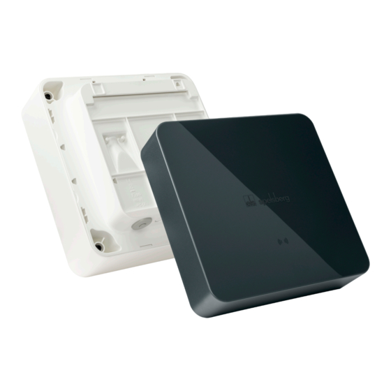
- Page 1 Wallbox Pure/Smart Pro Product manual Wallbox Pure/Wallbox Smart Pro...
-
Page 2: Table Of Contents
Setup................20 10.1. Installing the Spelsberg wallbox app......................20 10.2. - Page 3 Troubleshooting..............32 14.1. Reading out faults (Wallbox Pure)....................... 32 14.2.
-
Page 4: About These Instructions
About these instructions Read these instructions carefully before assembly and operation and keep them in a safe place. Give them to the new user if the product is passed on. More information on the product, details and technical knowledge can be found on our website. 1.1. -
Page 5: General Safety
2.1. General safety Warnung Risk of fatal electric shock ► If the wallbox or the connected cables are visibly damaged, take the wallbox out of operation. ► If the connected cables and lines of the wallbox are damaged, have them replaced by a qualified specialist company to avoid hazards. -
Page 6: Tasks According To Group
The wallbox is suitable for indoor and outdoor use. The wallbox is intended for mounting on a wall or pedestal. Only pedestals provided by Spelsberg may be used for mounting. The wallbox must be operated in accordance with the applicable international and national regulations. -
Page 7: Accessories
Overload (Smart Pro only) „ Overvoltage / undervoltage (Smart Pro only) The Spelsberg wallbox app helps the installer to configure the wallbox and offers the operator and users a variety of functions for controlling the wallbox and analysing the charging processes: „... -
Page 8: Controls And Connections
The Smart Pro wallbox can be connected to the internet using the following options: „ LAN (standard) „ WLAN 7.1. Controls and connections Fig. 2: General view Item Description Nameplate (under the design cover) Status LED, buzzer and RFID reader Charging cable Cable management 7.2. -
Page 9: Cable Entries
7.3. Cable entries Fig. 4: Knockouts and factory installed cable entries DMS in the enclosure The wallbox has a number of cable entries. Some of the cable entries are equipped with double membrane seals (DMS). The remaining cable entries are designed as knock-out membranes and can be opened if necessary. -
Page 10: Installation
There must be at least 250 mm free space around the wallbox. This includes plant growth. „ Spelsberg recommends keeping a sufficient distance to other obstacles in the installation area. „ The bottom of the wallbox must be at least 900 mm above the ground. -
Page 11: Preparing For Installation
You will need the following tools for installation: „ Electric drill „ Screwdrivers (suitable for the fastening screws and cover screws) „ Spirit level „ Pencil „ Side cutter „ Wire stripper „ Crimping tool 9.3. Preparing for installation ► Only for cable entry through the back wall: Unscrew the enclosure cover from the wallbox. -
Page 12: Checking The Connectors
9.4. Checking the connectors Fig. 6: Charge controller connections Item Description Item Description Connection for plug A (PE, CP, ...) Connection for measuring current transformer Connection for LAN (LAN-2, Smart Pro only) Connection for 2-phase disconnection (Smart Pro only) Connection for LAN (LAN-1, Smart Pro only) Connection for PV enabling contact (Smart Pro only) 2x USB type A (HMI board connection) - Page 13 150 mm Fig. 8: Marking the fastening points for the mounting rail ► Mark the fastening points for the mounting rail (Fig. 8). ► Drill the holes for the fastening points. ► Insert the wall plugs into the holes. ► Screw on the mounting rail.
- Page 14 Fig. 10: Drilling holes for the fastening points ► Drill the holes for the fastening points. ► Insert the wall plugs into the holes. ► Only for cable entry through the base: Lay the required cables (e.g. power supply, LAN cable). ►...
-
Page 15: Connecting The Charging Cable
9.6. Connecting the charging cable >1 cm Fig. 12: Connecting the charging cable ► Unfasten the strain relief. ► Feed the charging cable through the bottom right DMS M25 and the strain relief clamp. ► Pull the charging cable back slightly so that the DMS forms a downward funnel. The sheath of the cable must still protrude at least 1 cm from the strain relief. -
Page 16: Connecting The Supply Cable
9.7. Connecting the supply cable Warnung Risk of fatal electric shock There is a risk of electrocution if the electrical supply cable is not properly connected. ► Always have the electrical supply cable connected by a locally authorised electrician. ► Install a suitable residual current circuit breaker and line fuse in the supply line. - Page 17 Achtung Risk of damage to the wallbox Incorrect wiring can damage the wallbox. ► Ensure a clockwise rotating magnetic field for a 400 V power supply. ► For a 1-phase wallbox, always connect the 230 V power supply to L1. ►...
-
Page 18: Connecting The Pv System Signal Line (Optional, Wallbox Smart Pro Only)
Place the cable on the spring terminals. Note The connection of the inverter of the photovoltaic system to the wallbox must be parametrised in the Spelsberg wallbox app (See 10.6.4. Parametrising a PV system, page 24). 9.9. Connecting the LAN (optional, Smart Pro wallbox only) -
Page 19: Testing The Insulation Resistance
9.10.1. Testing the insulation resistance ► Disconnect the following plugs and cables inside the wallbox: • Contactor control connection on the charge controller (Fig. 6, 9) • Supply voltage connection on the charge controller (Fig. 6, 10) • Smart Pro wallbox only: N conductor on the MID meter (terminal 10). ►... -
Page 20: Setup
13 or higher, e.g. iPhone 7 or newer. ► Download the Spelsberg wallbox app from the Play Store or App Store and install it on the smartphone. Alternatively, use the following QR code link to access the app:... -
Page 21: Instructions For Installers On Commissioning And Configuring The Wallbox Via Smartphone And Nfc
LED. ► If the card wallet on the smartphone opens, the wallbox is not in NFC mode. Follow the instructions in the app or check the FAQ section on the Spelsberg website. ► Start the app. ►... -
Page 22: Setting The Charging Current
Warnung The user does not have restricted access rights and can therefore set all parameters. ► Technical values may only be set by a qualified electrician. ► Start the app. ► Select the menu item “Add wallbox to app”. ► Scan the provided setup QR code with the smartphone to save the wallbox data in the app. -
Page 23: Network Connection Via Wlan
For more information on load management, visit the Spelsberg website. 10.6.2. Energy management system The Spelsberg wallbox can be integrated into an energy management system. This will adjust the charging process according to the available energy. ► Select the menu item “System” → “Settings” → “Advanced settings” → “Energy management systems”. -
Page 24: Ocpp Backend
10.6.3. OCPP backend The Spelsberg wallbox can communicate with an OCPP backend. Charging processes are then reported to the backend, and the wallbox can be controlled by the backend. ► Select the menu item “System” → “Settings” → “Advanced settings” → “OCPP backend”. -
Page 25: Operation
Operation Gefahr Risk of death, serious injury and burns Dangerous arcing can cause death or serious injury. ► Never pull the vehicle charging plug out by force. Depending on the wallbox and electric vehicle, the ending of the charging process and the time it takes to unlock may vary. Warnung Risk of death, serious injury and burns Incorrect handling of the charging cable can cause explosions, electric shocks and short circuits. -
Page 26: Status Led And Buzzer
11.1. Status LED and buzzer An LED and a buzzer in the enclosure cover indicate the status of the wallbox. Display Status Description Buzzer signal Recommended action START The wallbox starts up. ► Wait until the wallbox is ready for use. Continuous loop READY The wallbox is ready for the charging process. -
Page 27: Charging An Electric Vehicle
11.2. Charging an electric vehicle Achtung Risk of fatal electric shock Moisture or damaged cables and plugs can cause electric shock. ► Before using them, make sure that the supply line, plug and charging socket are clean and dry. ► Never touch the plugs if your hands are wet or you are standing in water. -
Page 28: Ending The Charging Process
To use the app, it has to have been set up (“Set up as operator”). This requires the setup QR code. Once this has been successfully done, the Spelsberg wallbox app is available, either in the home network (Smart Pro), or via NFC with limited functionality. -
Page 29: Configuring Charging Authorisations
Spelsberg wallbox app”, page 20). 11.4.1. Configuring charging authorisations Authorisations can be set up and managed using the Spelsberg wallbox app. If you do not want to allow un- restricted use of the wallbox, you can create authorisations for vehicles and RFID chips. ►... -
Page 30: Updating The Firmware (Offline)
The firmware updates of the charge controller for the networked Smart Pro variants take place automatically in the background and are managed by Spelsberg. As the operator of the wallbox, you do not have to perform any action and are regularly provided with new functions and bug fixes. The current firmware version of the wallbox is displayed in the app under the menu item “System”... -
Page 31: Reading Out Faults (Wallbox Pure)
► Read out the fault codes with the Spelsberg wallbox app: • Via NFC (Pure and Smart Pro) See 14.1. Reading out faults (Pure wallbox)., page 31 • Via LAN / WLAN (Smart Pro only) See 14.2. Reading out faults (Smart Pro wallbox), page31 14.1. -
Page 32: Genuine Spare Parts
15.3. Genuine spare parts Spelsberg offers the following spare parts: 5m charging cable with type 2 plug 591 809 01 7m charging cable with type 2 plug 591 810 01 Polar design cover 591 811 01 Graphite design cover 591 812 01... -
Page 33: Replacing The Design Cover
15.5. Replacing the design cover 15.5.1. Removing the design cover To remove the design cover you need: „ At least 2 discs or suitably sized coins. 15.5.2. Fig. 21: Removing the design cover ► Release the design cover using the discs (Fig. 21). To do this, insert the discs as far as they will go into the release holes on the back. -
Page 34: Mounting The Design Cover
Make sure that the RFID logo is not covered (with stickers or tape, for example). Otherwise, the NFC functionality may be impaired. ► Press the design cover onto the wallbox. The Spelsberg logo must be legible (see Fig. 22). The design cover snaps into the hooks on the side panels of the wallbox. -
Page 35: Replacing The Cover Retainer
15.6. Replacing the cover retainer Fig. 23: Replacing the cover retainer If the cover retainer has visible defects, it must be replaced. ► Cut the old cover retainer in the middle. ► Using a small screwdriver, push the lugs of the part of the retainer left in the cover and pull it out of the cover on the other side. -
Page 36: Deinstallation
Deinstallation Warnung Risk of fatal electric shock There is a risk of electrocution when working on the electrical components of the wallbox. ► All work on the electrical components of the wallbox must be carried out by a locally certified electrician. ►... - Page 37 Pure Smart Pro Pollution level Protection class Wallbox overvoltage category Charging cable overvoltage category Communication interfaces/protocols NFC, USB NFC, USB, WLAN, Ethernet, OCPP 1.6, Modbus, EEBus, SMA SEMP Charging authorisation RFID RFID, EVCCID MID meter Load management Dynamic ISO15118 Plug & Charge AutoCharge Automatic phase switching In preparation...
- Page 40 Affix setup QR code here Günther Spelsberg GmbH + Co. KG Head office Im Gewerbepark 1, D-58579 Schalksmühle Postfach 15 20, D-58571 Schalksmühle Tel.: +49 (0) 23 55 / 8 92-0 Fax: +49 (0) 23 55 / 8 92-299 Visit us on Facebook E-mail: info@spelsberg.de...
Need help?
Do you have a question about the Wallbox Pure and is the answer not in the manual?
Questions and answers