Advertisement
Quick Links
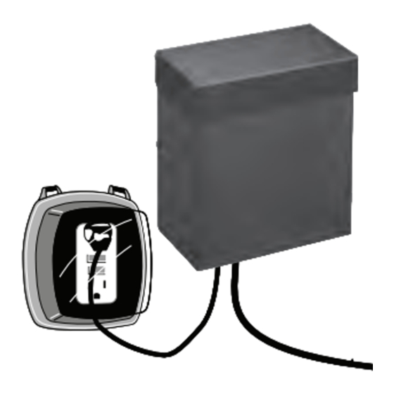
ML600TW Model / Modelo / Modèle
POWER PACK / TRANSFORMADOR / BLOC D'ALIMENTATION
WARNING: Risk of Fire or Electrical Shock
•
Mount power pack vertically at least one foot above ground. Do not lay
on the ground.
•
Plug power pack directly into an outdoor GFCI outlet with a weather-
proof cover marked "wet location." Do not use extension cords.
•
Mount power pack at least 10 feet from pool or spa.
•
When connecting wire at terminals, do not allow insulation to get under
the clamping plate, and firmly tighten the terminal screws.
•
Do not use cable smaller than listed in the table below.
•
Do not coil extra cable around the power pack. Either cut off extra
cable and discard, or leave at the end away from the power pack.
•
Do not repair or tamper with cord or plug.
•
Do not submerge power pack.
•
Do not connect two or more power packs in parallel.
•
Do not use with a dimmer.
•
If house circuit breaker trips when power pack is turned on, unplug
power pack from AC outlet, correct fault, restore power, then reset
circuit breaker.
•
Power pack and fixtures must be installed in compliance with national
and all local electrical codes and ordinances.
•
If necessary to splice cable, carefully follow instructions that came
with the connector you have purchased.
1
Select Cable
Use chart at right to
Power Pack Wattage
Minimum Gauge Cable
determine the mini-
217-300
mum gauge cable to
157-216
14-12
be used, depending
on the wattage of
121-156
16-14-12
the power pack. Us-
0-120
18-16-14-12
ing larger cable will
ML600TW consists of two 300 watt terminal blocks.
increase light output.
For Malibu cable, contact your supplier. WARNING—RISK OF FIRE:
Do not use cable smaller than listed in the table.
2
Place Fixtures
Lay the fixtures out where you want to locate them. The first
fixture should be at least 10 wire feet from the power pack. Mount
them permanently if you wish. WARNING—RISK OF ELECTRICAL
SHOCK: Do not place a fixture within 10 feet of a pool or spa.
3
Prepare Cable
5/8"
5/8"
Malibu cable is prepared, ready to con-
3"
3"
nect to the power pack. If using other
cable, split one end of cable for about
3", being careful when splitting NOT to
expose the copper wire. Then strip 5/8"
of insulation from the end. Also, refer to
strip length guide on the power pack.
4
Connect Cable to Power Pack
Lay power pack on a flat, stable surface and insert
the stripped end of one wire under terminal clamp-
ing plate A. Then tighten the screw. Repeat this
procedure for clamping plate B. Do not exceed the
wattage rating of the power pack. NOTE: The C
terminal is only used to connect an optional photo
control. WARNING—RISK OF FIRE: Make sure there is no wire
insulation under the clamping plate, and firmly tighten the terminal
screws.
5
Mount Power Pack
Mount power pack vertically outdoors
only. WARNING—RISK OF FIRE OR ELEC-
TRICAL SHOCK: Make sure Power Pack is
at least 1 foot above ground and at least
10 feet from pool or spa. Plug into GFCI
outdoor electrical outlet protected by a
weatherproof cover (not supplied–Malibu
recommends genuine Intermatic weather-
proof covers). Make sure outlet is working.
6
Run Cable
Route the low-voltage cable to fixtures. If there is extra cable, coil it
after last fixture or cut it off and discard. If you are using cable that
came with power pack and fixtures, leave about 12" of cable after
the last fixture. Be sure to leave at least 10 wire feet between the
power pack and first fixture. Do not yet hide or bury cable. WARN-
ING—RISK OF FIRE: Do not coil cable around power pack.
7
Turn Power Pack ON
Locate the manual ON/OFF switch on power pack and move it to
the ON position.
8
Attach Fixtures to Cable
Attach fixtures to cable using cable connectors as
shown. Place one connector on each side of cable,
then press together to lock. Prongs will pierce cable
to make contact, and fixture should light up.
12
9
Set Timer ON / OFF Times
Set ON and OFF times by setting tripper locations:
a.
Insert a red ON tripper (A) at the time you want
the lights to turn on.
b.
Insert a black OFF tripper (B) at the time you
want the lights to turn off.
c.
Use a second set of red and black trippers if you
want another ON/OFF cycle.
10
Set Time of Day
Set time of day on the timer as follows:
a.
Make sure the Power Pack is plugged in and
turned ON.
b.
Turn the dial to the present time of day as
shown by the arrow (C).
c.
Turn the dial one or more complete revolutions,
then return to the present time of day.
The lights will now turn ON and OFF at the times you have set.
You can manually operate the lights by turning the Manual ON/OFF
Switch (D).
11
Protect or Hide Cable
Once all fixtures are in place and you are satisfied with their loca-
A B C
A B C
tions, cable may be protected by covering or burying up to 3" deep.
Remember, if you are using cable that came with the power pack
and fixtures, leave about 12" of cable after the last fixture and lay
excess cable between fixtures. WARNING—RISK OF FIRE: Do not
Terminal Blocks
Terminal Blocks
coil excess cable except after the last fixture.
READ INSTRUCTIONS BEFORE
USING THIS PRODUCT.
Suggestions to Solve Problems Quickly
•
Make sure power pack is plugged in. Is outlet working?
•
Turn timer manual switch to "ON" or rotate dial so "ON" tripper passes
time line indicator.
GFCI
GFCI
•
Is lamp burned out? Use another lamp to test.
NOTE: This lighting system is designed to last many years under normal
conditions. However, lamps eventually burn out and operating with one
12"
12"
lamp out can shorten the life of the others. Conditions beyond control
(high input voltage, poor voltage regulation, etc.,) will also affect lamp
life. IT IS IMPORTANT TO REPLACE BURNED OUT LAMPS PROMPTLY.
ADVERTENCIA: Peligro de incendio o descarga eléctrica
•
Instale el transformador en forma vertical al menos un pie (30 cm) sobre
el suelo. No lo instale en el suelo.
•
Conecte el transformador directamente a un tomacorriente GFCI exte-
rior protegido por una cubierta protectora contra la intemperie marcada
como apta para "lugares humedos". No use cables de extensión.
•
Instale el transformador al menos a 10 pies (3 m) de la piscina o spa.
•
Al conectar el cable a las terminales asegúrese que el aislante no se
encuentre debajo de la placa de fijación y los tornillos de la terminal
estén firmemente ajustados.
•
No use cables más pequeños de los que se mencionan en la tabla que
aparece a continuación.
•
No enrolle el cable sobrante alrededor del transformador. Puede cortar
el cable sobrante y desecharlo o bien, dejarlo hasta el extremo lejos
del transformador.
•
No repare ni modifique de ninguna manera el cable o enchufe.
•
No sumerja el transformador.
•
No conecte dos o más transformadores en paralelo.
B
B
•
No lo utilice con un atenuador de luz.
•
Si el cortacircuito salta cuando se enciende el transformador, des-
enchúfelo del tomacorriente de CA, corrija la falla, vuelva a restablecer
A
A
la red eléctrica y active nuevamente el cortacircuito.
•
El transformador y las lámparas se deben instalar de acuerdo con todos
los códigos y normas nacionales y locales.
•
Si es necesario empalmar cables, siga atentamente las instrucciones
que se incluyen con el conector que adquirió.
D
D
C
C
1
Selección de un cable
Use la tabla
Vatiaje del transformador
que aparece
217-300
a la derecha
157-216
para determi-
nar el calibre
121-156
mínimo del
0-120
cable que
ML600TW consta de dos bloques de terminales de 300 watts.
se va a usar,
dependiendo del vatiaje del transformador. Al usar un cable más
grande aumentará la emisión luminosa. Para conseguir un cable de
Malibu, comuníquese con su proveedor. ADVERTENCIA—PELIGRO
DE INCENDIO: No use cables más pequeños de los que se mencio-
nan en la tabla.
2
Instalación de las lámparas
Instale las lámparas en el lugar deseado. La primera lámpara se
debe instalar a una distancia mínima de 10 pies (3 m) del transfor-
mador. Si lo desea instálelas en forma permanente. ADVERTEN-
CIA—PELIGRO DE DESCARGA ELÉCTRICA: No instale una lámpara
a menos de 10 pies (3 m) de una piscina o spa.
LEA LAS INSTRUCCIONES ANTES
VEUILLEZ LIRE LES DIRECTIVES
DE USAR ESTE PRODUCTO.
AVANT D'UTILISER CE PRODUIT.
For Missing / Damaged Parts from Newly Purchased Products:
Si el producto que acaba de adquirir está incompleto o tiene piezas dañadas, noti-
fique el problema a través de:
En cas de pièces manquantes / endommagées dans des produits tout neufs:
www.intermatic.com/warranty or/o/ou 1-800-492-2289
For Customer Service or To Purchase Replacement Parts, call:
3
Preparación del cable
El cable de Malibu está preparado, listo
para conectarlo al transformador. De lo
contrario, si usa otro cable, separe un
extremo del cable aproximadamente 3
pulgadas (7,6 cm), tenga cuidado cuando
lo separe de NO exponer el hilo de co-
bre. Después, retire 5/8 pulgadas (16 mm) del aislante del extremo.
Consulte la guía de longitud de desforre del transformador.
4
Conexión del cable al transformador
Instale el transformador en una superficie plana y
estable e inserte el extremo sin material aislante
debajo de la placa de fijación del terminal A. Lu-
ego, apriete el tornillo. Repita este procedimiento
para ajustar la placa de fijación B. No exceda la
capacidad nominal de vatiaje del transformador.
NOTA: El terminal C se usa sólo para conectar un control fotoeléc-
trico opcional. ADVERTENCIA—RIESGO DE INCENDIO: Asegúrese
que el aislante no se encuentre debajo de la placa de fijación y los
tornillos de la terminal estén firmemente ajustados.
5
Instalación del transformador
Instale el transformador en forma verti-
cal en exteriores solamente. ADVERTEN-
CIA—PELIGRO DE INCENDIO O DESCARGA
ELÉCTRICA: Asegúrese de instalar el
transformador al menos 1 pie (30 cm) sobre
el suelo y por lo menos a 10 pies (3 m) de
una piscina o spa. Conéctelo a un tomacor-
riente eléctrico GFCI exterior protegido por
una cubierta protectora contra la intemperie
Calibre mínimo del cable
(no se incluye, Malibu recomienda cubiertas protectoras contra la
12
intemperie originales de Intermatic). Asegúrese de que el tomacor-
14-12
riente esté en buen estado.
16-14-12
18-16-14-12
6
Cable tendido
Extienda el cable de bajo voltaje hasta las lámparas. Si sobra cable,
enrolle el cable sobrante después de la última lámpara o córtelo y
deséchelo. Si está usando el cable que viene con el transformador y
las lámparas, deje aproximadamente 12 pulgadas (30 cm) de cable
después de la última lámpara. Asegúrese de dejar al menos 10 pies
de cable entre el transformador y la primera lámpara. No oculte ni
entierre el cable todavía.
ADVERTENCIA—PELIGRO DE INCENDIO: No enrolle el cable so-
brante alrededor del transformador.
1-815-675-7000
16 mm
16 mm
7.6 cm
7.6 cm
Bloques de Terminales
Bloques de Terminales
GFCI
GFCI
30 cm
30 cm
158ML12900
Advertisement

Related Manuals for Malibu Boats ML600TW


Summary of Contents for Malibu Boats ML600TW
-
Page 1: Conexión Del Cable
0-120 18-16-14-12 cable que ML600TW consta de dos bloques de terminales de 300 watts. se va a usar, dependiendo del vatiaje del transformador. Al usar un cable más grande aumentará la emisión luminosa. Para conseguir un cable de Malibu, comuníquese con su proveedor. -
Page 2: Installation
Si en un plazo de cinco (5) años contados a partir de la fecha de compra, el producto falla debido a un defecto de material o mano de obra, Intermatic Incorporated lo reparará o reemplazarrá, a opción propia, de forma gratuita. Esta garantía se aplica solamente al comprador particular original y no es transferible.
Need help?
Do you have a question about the ML600TW and is the answer not in the manual?
Questions and answers
Where the power fuse located on Malibu ML600TW?
The power fuse location on the Malibu Boats ML600TW is not specified in the provided context.
This answer is automatically generated