Table of Contents
Advertisement
Quick Links
M300DP L Series Expansion I/O Module – Installation / User Manual
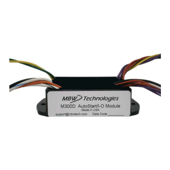
M300DP
Expansion I/O Module
AIt
for MBW L Series Control Panels
Installation / User Manual
M300DP Expansion I/O Module
AutoStart
with
P/N: MN10058-00
Email: sales@mbwtech.com
MBW
Technologies
, LLC
Phone: (267) 932.8573 x340
36
www.mbwtech.com
Copyright 2016 MBW Technologies, LLC All Rights Reserved
Advertisement
Table of Contents

Summary of Contents for MBW M300DP
- Page 1 M300DP L Series Expansion I/O Module – Installation / User Manual M300DP Expansion I/O Module for MBW L Series Control Panels Installation / User Manual M300DP Expansion I/O Module AutoStart with P/N: MN10058-00 Email: sales@mbwtech.com Technologies , LLC Phone: (267) 932.8573 x340 www.mbwtech.com...
- Page 2 (2) years from the date of shipment by MBW. Within this period, MBW will, at its sole option, repair or replace any Electronic Module or Display that fails in normal use and is returned to MBW (freight prepaid) within the warranty period.
-
Page 3: Table Of Contents
M300DP L Series Expansion I/O Module – Installation / User Manual M300DP L Series Expansion I/O Module – Installation / User Manual Table of Contents Index Quick Start Guide ....................... 5 A/S Mode ..........12 Recommended Order ....29 Block Diagram ........21 I/O Mode .......... -
Page 4: Connector
ABOUT M154. Hold MODE to view the software version screen. When the Auto Start module has been installed, the SW Version for the M300DP will also be displayed. If your software needs updating, contact your local distributor for the latest software revision. -
Page 5: Switch
M300DP L Series Expansion I/O Module – Installation / User Manual M300DP L Series Expansion I/O Module – Installation / User Manual Quick Start Guide Insert Auto Start Leads into the Engine Connector The Auto Start module provides six wire leads from the module to support two analog inputs, two discrete inputs and an alarm. -
Page 6: Powering The System
To power the system turn the key switch to the “ON” position. This will into the vacated pin location (Pin 3). activate the control panel and apply power to the M300DP module and the Remove the Green wire from the P3 connector and insert the engine ECU. -
Page 7: Mp300Dp System Operation
M300DP L Series Expansion I/O Module – Installation / User Manual M300DP L Series Expansion I/O Module – Installation / User Manual MP300DP System Operation Re-Assemble 9. Mount the Auto Start module. Menu Navigation 10. Connect the control panel connector (HDP24-21 connector) to the The Mode Button is multi-functional and is used as an escape and enter engine harness. -
Page 8: M300Dp Module Setup
(Yellow and Green) which go to the . NOTE: The M300DP Module menu selection will only be visible if the M300DP is correctly installed and has CANbus communication with the Also provided are six 6”... -
Page 9: I/O Mode Operation
AI1 and AI2 Setup in normal Start position Engine Connector. The M300DP Module has two analog inputs which may be configured for Engine cranks but does not fire when Check Engine manual for troubleshooting keyswitch is in normal Start position start issues. - Page 10 M300DP L Series Expansion I/O Module – Installation / User Manual M300DP L Series Expansion I/O Module – Installation / User Manual DI1 and DI2 Setup M300DP Main Menu – con’t The DI1 Setup and DI2 Setup are used to program the operation of the two discrete inputs.
-
Page 11: Io Status
M300DP L Series Expansion I/O Module – Installation / User Manual M300DP L Series Expansion I/O Module – Installation / User Manual Active State M300DP Main Menu – con’t The DI1 and DI2 inputs may be set for an input device that has either a Normally Open (N.O.) or Normally Closed (N.C.) contacts. -
Page 12: Auto Start Operation
M300DP L Series Expansion I/O Module – Installation / User Manual M300DP L Series Expansion I/O Module – Installation / User Manual Appendix A - Menu Overview Auto Start Operation Auto Start Mode (A/S Mode) M300DP Main Menu Selecting the A/S Mode allows the DI1 and/or DI2 discrete inputs to start and control the engine. -
Page 13: Speed Settings
M300DP L Series Expansion I/O Module – Installation / User Manual M300DP L Series Expansion I/O Module – Installation / User Manual Default Settings Speed Settings The A/S Mode supports three different engine speed settings. These Upon receiving the Auto Start module, the unit will be set to the following settings can be used in the throttle profile and in the remote speed values. -
Page 14: Digital Input Setup
M300DP L Series Expansion I/O Module – Installation / User Manual M300DP L Series Expansion I/O Module – Installation / User Manual Digital Input Setup Technical Specifications Parameter Specification The DI1 and DI2 Setup Operating Voltage 9 to 32 VDC... -
Page 15: Io Status
M300DP L Series Expansion I/O Module – Installation / User Manual M300DP L Series Expansion I/O Module – Installation / User Manual Wiring Diagram Active State Each digital input can be configured to determine its active state. This allows the user to set the digital input for an input device that has either a Normally Open (N.O.) contact or a Normally Closed (N.C.) contact. -
Page 16: Activating Autostart
Signal Enable Auto Start Mode Number Connector – P2 Size Color To use the Auto Start feature the M300DP Mode must be set to A/S. See M300DP – Alarm White/ the section on M300 Setup. Alarm (Switch Closure to Blue... - Page 17 M300DP L Series Expansion I/O Module – Installation / User Manual M300DP L Series Expansion I/O Module – Installation / User Manual When the Auto Start input is activated, the M150L Series will exit the Make External Connections power save mode and indicate an impending engine start sequence by To connect the two analog inputs and the two discrete inputs to the generating a countdown sequence to engine start.
-
Page 18: Typical Auto Start Application
M300DP L Series Expansion I/O Module – Installation / User Manual M300DP L Series Expansion I/O Module – Installation / User Manual Typical Auto Start Application Installing Control Panel with Expansion I/O Making the Connections The control panel has one round connector with 21 contacts. This connector is an HDP24 Deutsch connector and provides the connection to the engine connector.
Need help?
Do you have a question about the M300DP and is the answer not in the manual?
Questions and answers