Table of Contents
Advertisement
Quick Links
USER MANUAL
HATTELAND® SeaHawk IP Camera
HT FBVF yA-X1 (SeaHawk FixedBullet Varifocal)
HT ZB2X yA-X1 (SeaHawk ZoomBullet 20x)
HT FDFL yA-X3 (SeaHawk FixedDome Fixed Lense
where "Y" is housing Material
User Manual SeaHawk IP Camera
Updated: 04 Feb 2021
Created: 8370
Please visit www.hattelandtechnology.com for the latest electronic version of this manual.
Doc Id: INB101611-1 (Rev 01)
Approved: 8370
Advertisement
Table of Contents

Subscribe to Our Youtube Channel
Related Manuals for EMBRON HATTELAND TECHNOLOGY SeaHawk HT FBVF A-X1 Series

Summary of Contents for EMBRON HATTELAND TECHNOLOGY SeaHawk HT FBVF A-X1 Series
- Page 1 USER MANUAL HATTELAND® SeaHawk IP Camera HT FBVF yA-X1 (SeaHawk FixedBullet Varifocal) HT ZB2X yA-X1 (SeaHawk ZoomBullet 20x) HT FDFL yA-X3 (SeaHawk FixedDome Fixed Lense where “Y” is housing Material User Manual SeaHawk IP Camera Updated: 04 Feb 2021 Doc Id: INB101611-1 (Rev 01) Created: 8370 Approved: 8370 Please visit www.hattelandtechnology.com for the latest electronic version of this manual.
- Page 2 Copyright © 2020 Hatteland Technology AS Eikeskogvegen 52, N-5570 Aksdal, Norway. All rights are reserved by Hatteland Technology AS. This information may not, in whole or in part, be copied, photocopied, reproduced, translated or reduced to any electronic medium or machine- readable form without the prior written consent of Hatteland Technology AS.
-
Page 3: Table Of Contents
Contents Contents ..................3 General ..................5 About Hatteland Technology ...............5 www.hattelandtechnology.com ..............5 Contact Information ..................5 1. Introduction ................7 1.1 About this manual ..................7 1.2 Features ....................7 1.3 Product and Accessories ...............8 1.4 Contents of package ................9 1.5 System Connections ................10 2. - Page 4 Contents 5. Technical Drawings ............61 5.1 Technical Drawing: HT FBVF xx-X1 / HT ZB2X xx-X1 ..........62 5.2 Technical Drawing HT FDFL-xx-X3 ...............63 5.3 Technical Drawing HT CB1x-AA ................64 5.4 Technical Drawing HT WB1x-AA ................65 5.6 Technical Drawing HT MB1x-AA ................66 5.7 Technical Drawing LD-001 ..................69 Appendixes ................
-
Page 5: General
Hatteland Technology AS About this manual The manual contains electrical, mechanical and input/output signal specifications. All specifications in this manual, due to manufacturing, new revisions and approvals, are subject to change without notice. However, the last updated and revision date of this manual are shown both on the frontpage and also in the “Revision History” chapter. This user manual is a standard/general manual that applies to all variations of its product family, i.e. - Page 6 This page left intentionally blank...
-
Page 7: Introduction
1. Introduction 1.1 About this manual This User Manual provides information on operating and managing the Seahawk IP camera. The Manual includes instructions of installation, operation and configuration of Seahawk IP camera as well as how to troubleshoot. 1.2 Features Video Highly efficient compression algorithm, H.264, H.265 &... -
Page 8: Product And Accessories
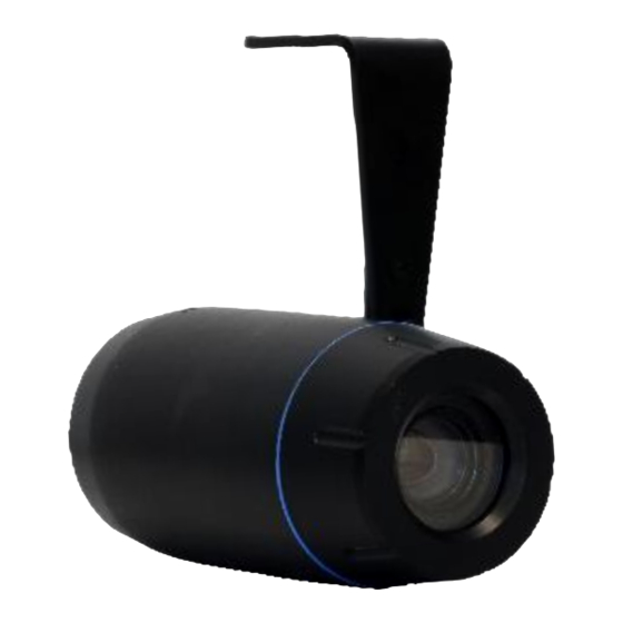
1.3 Product and Accessories HT FBVF xx-X1 HT FDFL xx-X3 HT ZB2X xx-X1 LD-001 HT CB1x-AA HT WB1x-AA HT MB1x-AA IND101057-27 3 Feb. 2021 Hatteland Technology AS | www.hattelandtechnology.com | Enterprise no: NO974533146 Page 8 of 66... -
Page 9: Contents Of Package
1.4 Contents of package Note: Entries listed below are for Standard factory shipments. Customized factory shipments may deviate from this list. Item Description Illustration RJ45 Waterproof Coupler shielded ø30 134.50 [5.29] This document is the property of Hatteland Technology AS. This document and any authorized reproduction thereof, must not be used in any way against the interest of Hatteland Technology AS. -
Page 10: System Connections
1.5 System Connections The Seahawk IP Cameras can be connected in either 1 to 1 connection where one SeaHawk Camera is connected to one PC client or a decoder system or 1 to many connections where one TN-B220xT.can be connected to several PCs and decoder systems. (TCS-2000 video server can work as a video decoder which takes the data from a video server or IP camera, decodes and outputs analog video.) Topology... - Page 11 One Seahawk camera is installed at a site where video images are transmitted. A PC or a decoder is installed at a central location to receive and view the video images on an analog monitor. Audio and serial data are transferred in either direction. 1:N Connection Site Remote Center...
-
Page 12: Installation
2. Installation 2.1 Connecting Network Plug network cable to Power over Ethernet port (RJ-45 network port). Once the power is supplied to the camera, it will start booting. The system will boot up to an operating mode after approximately 40-60 seconds. The green LED on the Ethernet port will flash indicating the system is ready. - Page 13 c. Right click on the Ethernet Port Connected to the Switch/Camera and left click “Properties”. d. Double click on “Internet Protocol Version 4 (TCP/IPv4), Check the box with “Use the Following IP address”. Now enter an IP address and Subnet mask into the fields. The IP address needs to be in the range of the cameras IP address: 192.168.1.
-
Page 14: System Operation
3. System Operation 3.1 Remote Video Monitoring There are two ways to monitor video when the center system and IP camera are connected. In order for a proper operation, an IP address must be set accordingly. Default password is requested modification for better security. Default ID : admin Default Password... -
Page 15: Live View Overview
Video Monitoring using RTSP Default: Primary stream: rtsp://192.168.1.90:554/video1 Secondary#1: rtsp://192.168.1.90:554/video2 Secondary#2: rtsp://192.168.1.90:554/video3 Custom address: 3.2 Live View Overview Select the Video stream to be viewed: Primary, Secondary #1, Video Select ◆ #2, #3. This video server is capable of quadruple streaming; primary streaming and secondary streaming #1~#3. - Page 16 Set preset position and move to the specific preset position if ◆ Select Preset PTZ Camera is connected to Video Server via Serial Port Set Goto: Move to the selected preset entry if the preset entry is set. Set: Set the current position to the selected preset entry. Clear: Delete the selected preset entry.
-
Page 17: Remote Configuration
4. Remote Configuration 4.1 Using Web Browser Remote setting is available by using web browser. Enter IP address of camera and then a live view screen appears as below. Press Setup button located in the upper right area of the monitoring screen to go to the server setup. -
Page 18: Video & Audio
Video & Audio Information Click to return to Live View Figure 3 Setup, Video & Audio, Information The information provides current information regarding the settings for video and Audio IND101057-27 3 Feb. 2021 Hatteland Technology AS | www.hattelandtechnology.com | Enterprise no: NO974533146 Page 18 of 66... - Page 19 Video Figure 4 Setup, Video & Audio, Video, Primary Performance Calculation Shows the performance usage rate according to the value set at ‘Encode’ mode underneath. Input Format User can select input format Algorithm Select compression algorithm and MJPEG is supported for only Secondary streams. Resolution Select video encoding solution.
- Page 20 1,2,3,4,5,6,8,10,15,20,25, 30 and 60 frame rate can be selected. The actual frame rate of video can be less than the maximum frame rate set due to the network bandwidth limitation Preference Select encoding mode to control video quality or bitrate: Quality(VBR) or Bit rate(CBR and Hybrid).
- Page 21 Secondary #1 ~ #2 Figure 5 Setup, Video & Audio, Video, Secondary#1 Use Dual Encode Select ON to enable to use Secondary #1 ~ #3. The Secondary #1 ~ #2 video can be viewed on Live View window by selecting Stream number on Video selection Algorithm Select H.264 or MJPEG or H.265 for the secondary, tertiary or quartic streaming.
-
Page 22: Image
Image General Figure 6 Setup, Image, General, Config Set#1, Exposure Exposure Exposure Target : Adjust setting values of exposure compensation for video ⚫ Exposure Mode : Select Advanced or Full Auto ⚫ Slow Shutter Mode : Adjust shutter mode ⚫ Shutter Range : Adjust shutter range ⚫... - Page 23 Semi Low Light: Similar to Auto. When low exposure, it opens the IRIS and setting maximum F.Number is allowed. Clear Mode: Based on brightness and Zoom magnification, operates as IRIS Auto. ☞Brighter or higher zoom magnification: IRIS Close ☞Darker or lower zoom magnification: IRIS Open F.
- Page 24 Color & Filter Figure 7 Setup, Image, General, Config Set#1, Color & Filter AWB Mode ⚫ Select Auto Tracing White, Auto White or Manual mode Brightness: Controls input video brightness by selecting values between 0 and 255 ⚫ Contrast: Controls input video contrast by selecting values between 0 and 255 ⚫...
- Page 25 Day & Night Figure 8 Setup, Image, General, Config Set#1, Day & Night The camera delivers color images during the day. As light diminishes below a certain level, the camera can automatically switch to night mode (Black & White mode) to maintain good image quality.
- Page 26 Schedule Figure 10 Setup, Image, Schedule In order to allow different configurations of the camera according to time of a day, the feature of defining camera configurations and scheduling them is provided Configuration Set ➢ 4 different configuration sets can be configured by opening the page with Config Set#N buttons.
- Page 27 Mask Figure 11 Setup, Image, Mask Masks can be displayed in the video. Position camera and select one of Masks from drop down menu. Press New button to get a mask and adjust mask size with the size buttons. The specified mark can be shown by Search button. IND101057-27 3 Feb.
- Page 28 IR Control Figure 12 Setup, Image, IR Control The IR Control only applies for Hatteland Seahawk FixedDome: HT FDFL xA-X3 Infrared LED control can be set to Auto or Manual Auto: When the camera changes to “Night mode”, the infrared LEDs turn on automatically. ⚫...
-
Page 29: Network
Network IP & Port Figure 13 Setup, Network, IP&Port Local Select the IP mode: Fixed IP or DHCP Depending on the selected mode, further configuration items comes as follows, IP Mode Selection Description Local IP Fixed IP address Fixed IP LocalGateway Gateway IP address Local Subnet... - Page 30 Obtain DNS server address automatically ➢ Get DNS server address automatically when IP mode is DHCP. Use the following DNS server address ➢ Enter the DNS server IP address; Primary or Secondary DNS server Domain Name System (DNS) is a database system that translates a computer's fully qualified domain name into an IP address.
- Page 31 RTSP Multicast - RTSP Multicast used to specify the multicast address to be used when the client requests RTSP multicast via ONVIF command. QoS (Quality of Service) - QoS guarantees a certain level of a specified resource to selected traffic on a network. A QoS-aware network prioritizes network traffic and provides greater network reliability by controlling the amount of bandwidth and application may use.
- Page 32 Discovery UPNP By the setting UPNP to ON, it allows the discovery by the clients according to UPNP (Universal Plug and Play) protocol. Zeroconf By setting Zerodonf to ON, it allows the discovery by the clients according to zeroconf protocol. WS Discovery Discovery function based on web service is enabled.
- Page 33 One-way Video Server provides two kinds of one-way (unidirectional) streaming based on UTP to clients; MPEG-TS and RTMP. Both are a kind of broadcasting where traffic from clients t o a server is not generated at all. MPEG-TS is a standard format for transmission and storage of audio, video, and data, an d is used in broadcast systems such as DVB and ATSC.
- Page 34 SRT (Secure Reliable Transport) - SRT is open source project which is Video and Audio transmission protocol developed by SRT Allicance. SRT optimizes streaming performance across unpredictable networks, such a s the Internet, by dynamically adapting to the real-time network conditions between transport endpoints.
- Page 35 SNMP Setup for using SNMP (Simple Network Management Protocol).It is compatible to both SNMPv1 and SNMPvec. Settings for using SNMP are as following; SNMP Listen Port (0, 161, 1025 ~ 65535) The port is for connecting external device when system operates as a SNMP client. SNMP is not used by setting 0 value.
- Page 36 DDNS Select DDNS (Dynamic DNS) server to use. One of the two can be selected. TrueDNS True DNS service is used in the mode. Systems can be registered on the website for http://ns1.truecam.net True DNS service, . A system will get a domain name of xxx.truecam.net.
- Page 37 IP filtering - IP filtering is simple mechanism that decides which types of IP datagrams will be processed normally and which will be discarded. IND101057-27...
- Page 38 E-mail E-mail Specify the information to send event information, when E-mail is selected as an eventaction. Server Address ➢ Enter an address of mail (SMTP) server Port ➢ Specify a port for SMTP operation (Port 25 is the default port in SMTP operation. If a different port is configured in the SMTP server, this port needs to be changed accordingly.) Sender Address...
- Page 39 E-mail Notification Video Clip Attaching ➢ Video clip stored at the moment of event can be attached as an AVI or JPEG file format. When dual or quadruple encoding is enabled, Primary video, Secondary video (H.264 only) or JPEG Capture can be selected. The number of JPEG frames is configured.
- Page 40 Specify the information to upload event information when FTP is selected as an event action. Server Address ➢ Enter an address of an RTP server to receive video files Port ➢ Specify a port for FTP operation (port 21 is the default port in FTP operation. If a different port is configured in the FTP server, this port needs to be changed accordingly.) ID &...
- Page 41 FTP Base Directory ➢ Specify the name of the directory to be created in the FTP server. It is valid only when Use Record is set to Use on Record session. FTP Test ➢ FTP upload function can be tested with this button. Please note that configuration settings should be saved first by pressing Apply button before using FTP test function.
- Page 42 SSL Enable ➢ SSL-VPN function will be enabled User ID ➢ User ID on VPN Client Password ➢ User Password on VPN client VPN IP Address ➢ Set IP address on VPN VPN Port ➢ Set the port on VPN VPN IP Address ➢...
-
Page 43: Event
Event Notification Local When a decoder instead of a PC client is connected to an IP camera, one system becomes a Local system and the other a Remote system (Generally a system which is being used by the user is called as Local system). Then, actions for events can be configured for events from the remote system as well as for local system. - Page 44 On Disconnection Configure the action when link (connection) with peer system is disconnected. Multiple actions can be set for a single event. User Defined Event User can configure the actions when User Defined Event occurs. IND101057-27 3 Feb. 2021 Hatteland Technology AS | www.hattelandtechnology.com | Enterprise no: NO974533146 Page 44 of 66...
- Page 45 User Defined Event 4.5.1.1.1.1.1.1.1 User can define events up to 4 and configure notifications on Notification page. IND101057-27 3 Feb. 2021 Hatteland Technology AS | www.hattelandtechnology.com | Enterprise no: NO974533146 Page 45 of 66...
- Page 46 Motion Detection Use Motion Detection Determine to use Motion Detection function. Motion Detection Area Editing Configure region for motion detection. Regions of arbitrary shape can be configured by the following steps; Select Enable on Edit tab. Select editing mode. Set is for including cells to motion detection region and Eras e is for excluding.
- Page 47 Alarm Set the duration of alarm activation in case of an event. If it is set to continuous, It will be in active until an operator reset it manually. IND101057-27 3 Feb. 2021 Hatteland Technology AS | www.hattelandtechnology.com | Enterprise no: NO974533146 Page 47 of 66...
- Page 48 Event OSD - User can create OSD in any position with above options with different colors. HTTP Action According to Event, Video Server will transmit HTTP API to Device. (User should put in H TTP API) Before starting this feature, please enable HTTP Action on Notification page IND101057-27...
-
Page 49: Record
4.6 Record General Use record Off : Recording function will not be used when “OFF” is selected. ➢ Use Disk : Use disk function will follow the setting of Schedule table which set as rec ➢ ord off as a default. Select Video Select video stream to record. - Page 50 Schedule Event Type Three recording modes are supported: Continuous, Event, Disconnect. In case of Event recording, event types can be selected among several events. Selected event type is used for configuring the schedule table. Up to 4 event types can be configured and each event type can be a combination of sensor, video loss and motion event.
-
Page 51: User
4.7 User User List User can be registered, and privilege level of a user can be specified. User configuration is allowed only to admin user. Max 16 users can be registered, and each user can have one of four privileges. Privilege Allowed Operations Remarks... - Page 52 Enter the current password and then set a new password. Modify Privilege Level Press Modify Privilege button to change User level. It is not allowed to change the privilege level of admin user. 3 Feb. 2021 Hatteland Technology AS | www.hattelandtechnology.com | Enterprise no: NO974533146 Page 52 of 66 IND101057-27...
- Page 53 Login Policy - Authentication Type HTTP authentication based on RFC 2617(HTTP Authentication: Basic and Digest Access Authentication) is supported. - Skip Login Skip Login provides for convenient access to the Video Server when authentication is not required. When Skip Login is set to Enable, login step is skipped. - Privilege Level After Login Skipped The privilege level after login in this way is determined by the setting of Privilege Level After Login Skipped.
-
Page 54: System
4.8 System Information System information Followed network information is displayed (Read only) Model ➢ Display the model name. Version ➢ Display the current firmware version. Mac Address ➢ Display the MAC address of the camera. In case the camera is registered at DDNS server, the MAC address is used in DDNS registration. - Page 55 Upgrade&Reboot Firmware Version : Display the current firmware version ➢ Upgrade: To upgrade firmware; 1. Press Browse button to select a firmware file from PC. 2. Press Firmware Upgrade button to start upgrading. 3. A message for showing status (downloading / upgrading) will be displayed. 4.
- Page 56 Stored configuration can be browsed and restored. The server is rebooted once Config Restore button is pressed. Reboot Reboot the camera ➢ Do not press the Reboot button unless the server needs a reboot. Factory Reset All settings including user accounts and logs are cleared Factory Reset Except Network Settings All settings except for current network settings are changed to the default values.
- Page 57 Time Start Time ➢ The latest the camera’s booting date and time. Current Time ➢ Current date and time. Enter a new date and time then press Set Current Time button to update date & time. Time Format ➢ Change the time format. The selectable time formats are as below; YYYY/MM/DD hh:mm:ss (Eg.
- Page 58 Display Time & OSD System ID Enter System ID that is used as a camera title. The set System ID is displayed with video image on a Web Browser. The System ID is also transferred to remote software, such as VMS, and displayed on it. Web Viewer OSD System ID and/or server time can be display over the video window in Internet Explorer.
- Page 59 2 : Both System ID and Time are displayed 1 : Either System ID or Time can be displayed. When both are enabled, System ID is displayed. 0 : No items are displayed. This is because video area is too small to display OSD text in large text.
- Page 60 Language Language Select the language to be used for web-based configuration. 3 Feb. 2021 Hatteland Technology AS | www.hattelandtechnology.com | Enterprise no: NO974533146 Page 60 of 66 IND101057-27...
-
Page 61: Technical Drawings
Technical Drawings... -
Page 62: Technical Drawing: Ht Fbvf Xx-X1 / Ht Zb2X Xx-X1
5.1: Technical Drawings - HT FBVF xx-X1 / HT IND100132-507... -
Page 63: Technical Drawing Ht Fdfl-Xx-X3
5.2: Technical Drawings - HT FDFL-xx-X3 IND100132-507... -
Page 64: Technical Drawing Ht Cb1X-Aa
5.3: Technical Drawings - HT CB1x-AA IND100132-507... -
Page 65: Technical Drawing Ht Wb1X-Aa
5.4: Technical Drawings - HT WB1x-AA IND100132-507... -
Page 66: Technical Drawing Ht Mb1X-Aa
5.6: Technical Drawings - HT MB1x-AA IND100132-507... - Page 67 5.6: Technical Drawings - HT MB1x-AA IND100132-507...
- Page 68 5.6 Technical Drawings - HT MB1x-AA IND100132-507...
-
Page 69: Technical Drawing Ld-001
5.7: Technical Drawings - LD-001 IND100132-507... -
Page 70: Appendixes
Return Of Goods Information Return of goods: (Applies not to warranty/normal service/repair of products) Hatteland Technology referenced as “manufacturer” in this document. Before returning goods, please contact your system supplier before sending anything directly to manufacturer. When you return products after loan, test, evaluation or products subject for credit, you must ensure that all accessories received from our warehouse are returned. -
Page 71: General Terms And Conditions
General Terms and Conditions As of January 2015, Hatteland Technology AS’ “Terms of Sales and Delivery” and “Warranty Terms” have been substituted by the updated ”General terms and conditions for sale of goods and performance of additional services” (the “General Terms and Conditions”). Further, from January 2015 onward, the previous “Terms of Sales and Delivery”... -
Page 72: Revision History
Revision History Rev. Date Notes 00_01 02 Mar 2020 Internal review release. Preliminary version 00_02 06 Nov 2020 Revised after internal reviews. 00_03 25 Jan 2021 Revised after internal reviews 04 Feb 2021 Release of User manual IND100077-254... - Page 73 Revision History IND100077-254...
- Page 74 Hatteland Technology AS | www.hattelandtechnology.com | Enterprise no: NO974533146...
Need help?
Do you have a question about the HATTELAND TECHNOLOGY SeaHawk HT FBVF A-X1 Series and is the answer not in the manual?
Questions and answers