Advertisement
Quick Links
Manual Contents
Safety Instructions
Assembly
Operation
Maintenance
Parts
Warranty
Caution:
Carefully read all rules and instruction for safe operation. Retain this manual for reference
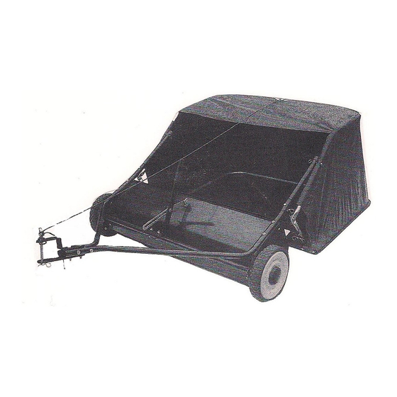
Owner's Manual | LSP48 | 48" Lawn Sweeper
Your Lawn Sweeper
2
Congratulations on your purchase of a new
4-13
Precision Products, Inc. Lawn Sweeper. Your Lawn
2
Sweeper has been engineered and built to give you
11
the most dependable and best performing product
14-15
possible.
16
If you experience any problem you can not easily
resolve,
knowledgeable
department toll-free at 1 (800) 225-5891.
please
feel
free
and
helpful
to
contact
our
customer
service
.
(Rev B) 7/13
Advertisement

Related Manuals for Precision LSP48

Summary of Contents for Precision LSP48
- Page 1 Owner’s Manual | LSP48 | 48” Lawn Sweeper Manual Contents Your Lawn Sweeper Safety Instructions Congratulations on your purchase of a new Assembly 4-13 Precision Products, Inc. Lawn Sweeper. Your Lawn Operation Sweeper has been engineered and built to give you...
- Page 2 Precision. At Precision Products, Inc. our goal is to deliver quality, value and outstanding service. If for any reason our product does not meet your expectations, please contact us and we will take care of any problem you may have with this unit.
- Page 3 Carton Contents pages 3 & 4 Ref. Qty. Description Ref. Qty. Description Bag Frame Strap Hitch Tube R.H. Hopper Support Rod Hitch Tube L.H. Lower Hopper Side Tube R.H. Handle Assembly Lower Hopper Side Tube L.H. Clevis Plate (straight) Upper Hopper Side Tube R.H. Clevis Plate Upper Hopper Side Tube L.
- Page 4 Ref. Qty. Description Ref. Qty. Description Clevis Pin 08x25 (Not Shown) Hex Head Bolt M8x65 Hitch Pin Hex Head Bolt M8x50 Hitch Spacer Hex Head Bolt M8x40 Angle Bracket Allen Head Bolt M6x30 Tube Plug Nylock Nut M8 Nylock Nut M6 Allen Head Bolt M6x35 Hitch Pin Clip 03 Clevis Pin 08x37...
- Page 5 Assembly Remove the Hardware Sack or (hardware may be attached to other parts) and all loose parts from the carton and verify that all the Parts and Fasteners shown on pages 3 and 4 are included. Assembly Instructions Note Right hand (R.H.) and Left hand (L.H.) are determined from the operator’s position while seated on the Tractor.
- Page 6 3. Attach the Hitch Tubes together using two M8x65 Hex Head Bolts and two M8 Nylock Nuts. Do not tighten yet. See Figure 3. R.H. Hitch Tube L.H. Hitch Tube M8x65 Hex Head Bolt Leave Gap In-between Tubing M8 Nylock Nut Figure 3 If your tractor hitch is between 11”...
- Page 7 6. Attach the Height Adjustment Handle to the Height Adjustment Tube, using two M8x40 Hex Head Bolts and two M8 Nylock Nuts. Do not tighten yet. See Figure 6. M8 Nylock Nuts Handle Grip Height Adjustment Handle Height Adjustment Tube M8 x 40 Hex Head Bolt Figure 6...
- Page 8 8. Insert a M8x30 Carriage Bolt into the Height Adjustment Handle, into a Washer, into the Height Adjustment Strap, place another Washer onto the Bolt and secure with the Plastic Knob. See Figure 8. Height Adjustment Strap Hitch Spacers 9. (Pre-Assembled At Factory) Assemble the Connecting Bar to the Sweeper Housing by using two M6x12 Hex Head Bolts and secure with two M6 Nylock Nuts.
- Page 9 10. Turn a Rear Hopper Tube so that the Brace Holes in the middle of the tube face down. Slide the tube through the two loops sewn to the top rear seam inside of the hopper bag. See Figure 10. M6x30 Bolt Upper Rear Hopper Tube...
- Page 10 13. Attach the ends of the Lower Hopper Side Tubes to the inside of the Upper Side Tubes using two 08x25 Clevis Pins, insert them from the inside and secure with two Hitch Pins Clips. See Figure 13. Upper Hopper Side Tube 08x25 Clevis Pin Hitch Pin Clip...
- Page 11 15. Secure the bag corners around the Lower Hopper Side Tubes by snapping the Bag Flaps to the Bag Bottom on both sides. See Figure 15. Flap Snap Figure 15 IMPORTANT: Do not over bend the Support Rods during the following step. Over bending will cause the steel rods to lose supporting tension.
- Page 12 17. Feel along the stitched flap on the Hopper Bag to locate the lower hole in each Upper Hopper Side Tube. Place a hole through both sides of the stitched flaps in alignment with the lower hole. See Figure 17. Upper Hole Lower Hole Upper Hopper...
- Page 13 19. Secure the Rope to the top center of the Hopper Bag Frame. See Figure 19. Top Center Hopper Bag Frame Rope Figure 19 20. Attach the Hopper Bag to the Sweeper, slide the ends of the Bag Arm Tubes into the ends of the Sweeper’s Hitch Tubes and secure with two 08x37 Clevis Pins and Hitch Pin Clips.
- Page 14 Exploded View...
- Page 15 Parts List LSP48 Part No. Description Qty. Part No. Description Qty. #1-38 Hopper Rope 40-48 Connecting Bar #2-38 Vinyl Cap 41-38 M6x12 Hex Head Bolt #3-48 Hopper Frame Tube (Rear) 42-38 Dust Cover Retainer #4-48 Bag Frame Strap 43-38 Inside Star Washer...
- Page 16 Manufacture’s Limited Warranty for Tow Behind Accessories The limited warranty set forth below is given by Precision forth in this warranty provide the sole and exclusive Products, Incorporated with respect to new merchandise remedy arising from the purchase. purchased and used in the United States, its possessions and territories.
Need help?
Do you have a question about the LSP48 and is the answer not in the manual?
Questions and answers