Table of Contents
Advertisement
Quick Links
Advertisement
Table of Contents

Related Manuals for Magnum Industrial MI-81570


Summary of Contents for Magnum Industrial MI-81570
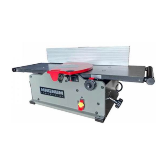
- Page 1 MODEL NO.: MI-81570 OPERATING MANUAL...
-
Page 2: Table Of Contents
TABLE OF CONTENTS INTRODUCTION SECTION 1 Warranty ....................3 SECTION 2 Product Specifications .................4 SECTION 3 Feature Identification ................4 SECTION 4 General Safety..................5 SECTION 5 Product Safety ..................8 SECTION 6 Grounding Instructions................10 SECTION 7 Unpacking & Inventory................12 SECTION 8 Assembly & Adjustments ……………………........13 SECTION 9 Cleaning Spiral Cutterhead &... -
Page 3: Product Specifications
PRODUCT SPECIFICATIONS Cutterhead speed RPM 12,000 Motor RPM 19000+/-10% (No Load) Cutterhead diameter 2" Max capacity 10" x 1/8" Cutter inserts qty Motor power input 120 V, 60 Hz, AC Only, 12 Amp Fence Size Overall 4 ⅜" x 24" Tables (Overall measurements) 10"... -
Page 4: General Safety
GENERAL SAFETY NOTE: The WARNING! and CAUTION! symbols indicate a potentially hazardous situation which, if not avoided, COULD result in death or serious injury. READ THIS MANUAL completely before assembling and operating this machine. WARNING! TO AVOID serious injury, death, or damage to the machine, please read, understand, and follow, all Safety and Operating Instructions before assembling and operating this machine. - Page 5 GENERAL SAFETY (cont.) ALWAYS keep the work area clean, well lit, and organized. DO NOT work in an area that has slippery floor surfaces from debris, grease, and wax. CAUTION! ALWAYS unplug the machine from the electrical receptacle when making adjustments, changing parts or performing any maintenance.
- Page 6 GENERAL SAFETY (cont.) KEEP protective guards in place and in working order. CAUTION! MAINTAIN your balance. DO NOT extend yourself over the tool. Wear oil resistant rubber soled shoes. Keep floor clear of debris, grease, and wax. MAINTAIN all machines with care. ALWAYS KEEP machine clean and in good working order. KEEP all blades and tool bits sharp.
-
Page 7: Product Safety
PRODUCT SAFETY Serious personal injury may occur if normal safety precautions are overlooked or ignored. Accidents are frequently caused by lack of familiarity or failure to pay attention. Obtain advice from supervisor, instructor, or another qualified individual who is familiar with this machine and its operations. -
Page 8: Grounding Instructions
GROUNDING INSTRUCTIONS WARNING! This machine MUST BE GROUNDED while in use to protect the operator from electric shock. In the event of a malfunction or breakdown, GROUNDING provides the path of least resistance for electric current and reduces the risk of electric shock. The plug MUST be plugged into a matching electrical receptacle that is properly installed and grounded in accordance with ALL local codes and ordinances. - Page 9 GROUNDING INSTRUCTIONS (cont.) Make certain the extension cord is properly sized, and in good electrical condition. Always replace a worn or damaged extension cord immediately or have it repaired by a qualified person before using it. Protect your extension cords from sharp objects, excessive heat, and damp or wet areas. MINIMUM RECOMMENDED GAUGE FOR EXTENSION CORDS (AWG) 115 VOLT OPERATION ONLY 25’...
-
Page 10: Unpacking & Inventory
UNPACKING & INVENTORY Check shipping carton and machine for damage before unpacking. Carefully remove packaging materials, parts and machine from shipping carton. Always check for and remove protective shipping materials around motors and moving parts. Lay out all parts on a clean work surface. Be EXTREMELY CAREFUL working around the cutter tips as they are VERY SHARP!!! Remove any protective materials and coatings from all of the parts and the jointer except for the cutterhead. -
Page 11: Assembly & Adjustments
ASSEMBLY & ADJUSTMENTS WARNING! MAKE CERTAIN THAT THE MACHINE IS DISCONNECTED FROM THE POWER SOURCE BEFORE ASSEMBLY AND ADJUSTMENTS FENCE ASSEMBLY PROCEDURE 1. Face the rear of the jointer and remove the 4 screws (A) using the provided 4mm Hex Wrench. See FIG 1 2. - Page 12 ASSEMBLY & ADJUSTMENTS (cont.) 3. Locate the Fence Sliding Bracket (E on page 12) and the 2 screws and 2 square nuts (G on page 12). Insert screws through the Fence Sliding Bracket upper holes “A” in FIG 3, and thread the square nuts on by hand about 3 compete turns.
- Page 13 ASSEMBLY & ADJUSTMENTS (cont.) 4. Locate fence (K on page 12) and slide from end, with the back of fence facing bracket, over the square nuts as shown in FIG 5. Note that the bottom of the fence is beveled and the square nuts have flats on them so you may have to rotate them slightly to slide the fence on.
- Page 14 ASSEMBLY & ADJUSTMENTS (cont.) 6. Facing the rear of the jointer, place the Sliding Bracket Fence Assembly onto the Fence Bracket and slide forward (towards front of the jointer) until the table holes are half exposed as shown in FIG 7. 7.
- Page 15 ASSEMBLY & ADJUSTMENTS (cont.) CUTTERHEAD GUARD The cutterhead guard has a tension return spring. The tension on this spring is set at the factory. When the guard is installed properly it should return to the fence automatically after the work piece has passed over the cutterhead. Be sure the guard is functioning properly every time before using the jointer.
- Page 16 ASSEMBLY & ADJUSTMENTS (cont.) FENCE ADJUSTMENTS The fence can be tilted from 90 to 135 degrees. There are 2 adjustable stop set screws for these limits. See FIG 17 for the location of these set screws. 1. To set the 90 degree stop, slightly loosen fence lever “B” and lift fence slightly clearing tables and slide fence forward approximately 1 inch.
- Page 17 ASSEMBLY & ADJUSTMENTS (cont.) 2. To set the 135 degree stop, loosen fence lever “A” and slide fence back completely and re-tighten lever “A”. Place a 45 degree angle against the fence and use the provided 2.5mm Hex Wrench to adjust the 135 degree set screw against the stop. NOTE: The set screw is set deep into the angled hole at the factory.
-
Page 18: Cleaning Spiral Cutterhead & Tips
CLEANING SPIRAL CUTTERHEAD & TIPS WARNING! MAKE CERTAIN THAT THE MACHINE IS DISCONNECTED FROM THE POWER SOURCE BEFORE PERFORMING ANY MAINTENANCE PROCEDURES WARNING! To prevent serious personal injury NEVER rotate the cutterhead by hand. Cutter tips are razor sharp! Always wear heavy leather gloves when handling the cuttherhead. - Page 19 CLEANING SPIRAL CUTTERHEAD & TIPS (cont.) Step 3 - Separate the tips from the screws and place in separate containers with a bit of mineral spirits or non-chlorinated brake cleaner. Once all are removed, wipe down the bare cutterhead using rags with whichever solvent you chose. Once the oil is wiped off, use an air compressor or a can of pressurized air to clear each seat and screw hole on the cutter head.
-
Page 20: Operations
OPERATIONS NOTE: This operations section was designed to give instructions on the basic operations of this jointer. However, it is in no way comprehensive of every jointer operation. It is strongly recommended that you read books, trade magazines, or get formal training to maximize the potential of your jointer while minimizing the risks. - Page 21 OPERATIONS (cont.) DIRECTION OF GRAIN Avoid feeding work into the jointer against the grain. The result will be chipped and splintered edges or tear out. Feed with the grain to obtain a smooth surface. See FIG 25 FIG 25 The jointer can be set to cut any depth from a very thin shaving to 1/8” deep. The pointer on the scale is to indicate the depth of cut.
- Page 22 OPERATIONS (cont.) PLACEMENT OF HANDS DURING FEEDING At the start of the cut, the left hand holds the work against the infeed table and fence, while the right hand pushes the work down and toward the knives. After the cut is underway, the new surface rests on the outfeed table.
- Page 23 OPERATIONS (cont.) JOINTING AN EDGE This is the most common operation for the jointer. These cuts are made to square an edge of a work piece. Set the guide fence square with the table. Depth of cut should be the minimum required to obtain a straight edge.
- Page 24 OPERATIONS (cont.) UNDESIREBALE RESULTS NOTE: Rough sawn , bowed, cupped, or twisted stock will take several passes before a smooth finish is achieved. If you are getting scalloping (aka chatter marks) on the surface of your stock, this is due to error of the operator feed speed.
-
Page 25: Maintenance
MAINTENANCE WARNING! MAKE CERTAIN THAT THE MACHINE IS DISCONNECTED FROM THE POWER SOURCE BEFORE PERFORMING ANY MAINTENANCE PROCEDURES Your jointer should provide you with a long time of service provided you take the time to perform the following maintenance operations. CLEANING Sawdust buildup and other debris can cause the tool to joint and plane incorrectly. - Page 26 MAINTENANCE (cont.) WARNING! MAKE CERTAIN THAT THE MACHINE IS DISCONNECTED FROM THE POWER SOURCE BEFORE PERFORMING ANY MAINTENANCE PROCEDURES CUTTER TIP REPLACEMENT – USE PAGES 20 - 21 FOR REFERENCE IF NECESSARY WARNING: To prevent serious personal injury NEVER rotate the cutterhead by hand. Cutter tips are razor sharp! Always wear heavy leather gloves when handling the cutterhead.
- Page 27 MAINTENANCE (cont.) DISCONNECT THE JOINTER FROM THE POWER SOURCE! Remove any sawdust from the head of the Torx screw. ◼ Remove the Torx screw and Cutter insert. ◼ Clean all dust and dirt off the cutter insert and the cutterhead pocket from which the cutter ◼...
- Page 28 MAINTENANCE (cont.) 3. Loosen the 3 motor mounting screws “A”, “B” and “C”, about 1 full turn. See FIG 30 4. From the exposed open base, gently push motor away from you with left hand to release belt tension and rotate the belt to walk the belt off the motor pulley with your right hand. See FIG 31...
- Page 29 MAINTENANCE (cont.) 5. Place new belt over cutterhead pulley and walk belt onto the motor pulley. Make sure that the belt is seated in all cutterhead and motor pulley grooves. Pull right side of motor, to begin tensioning belt, and snug up screw “C”. Do not securely tighten “C” at this time. See FIG 32 6.
-
Page 30: Troubleshooting
TROUBLESHOOTING GUIDE INFEED / OUTFEED TABLE COPLANAR AND CUTTERHEAD PARALLELISM CHECK NOTE: Do not attempt these adjustments before running a piece of test stock to make sure there is an issue with the jointer and not an operator or a set up error. The infeed and outfeed tables have been adjusted at the factory before shipment. - Page 31 TROUBLESHOOTING GUIDE (cont) 2. Lower the infeed table to its lowest setting by rotating Infeed Table Lock Knob “A” counterclockwise to loosen and rotate the Infeed Table Lower/Raise Knob “B” clockwise to lower the table. See FIG 12 3. Place a metal straight edge at least 24” in length on the outfeed table across the cutterhead near the fence and over the cutterhead tip nearest the fence to check for parallelism.
- Page 32 TROUBLESHOOTING GUIDE (cont) 4. If the outfeed table is not level (parallel) with the cutterhead tips, slightly loosen the 4 table mounting screws (A) with the larger hex wrench. See FIG 15. Next to each mounting screw are 2 adjustable set screws (B & C) that allow you to adjust the table up or down. See FIG 16 5.
- Page 33 TROUBLESHOOTING GUIDE (cont) Once the outfeed table is adjusted properly, and parallel with the cutterhead tip edges, tighten down all 4 mounting bolts and recheck all 8 set screws to make sure they contact the surface under the table. Again, this is done by feel and not visible. 6.
- Page 34 TROUBLESHOOTING GUIDE (cont) INFEED / OUTFEED EXTENSION SUPPORT ADJUSTMENT The infeed and outfeed extension supports are adjustable for coplanar or parallelism if ever necessary. These are set at the factory. If after planing or edge joining a work piece, an adjustment is necessary, follow these instructions.
- Page 35 TROUBLESHOOTING GUIDE (cont) PROBLEM LIKELY CAUSE SOLUTION Motor will not start. Not plugged in. Check the power source. Blown circuit. Replace fuse, reset breaker, or call Lockout key removed. electrician. Improper Voltage. Replace yellow safety key. Fuses or circuit Short circuit in line cord or plug. Call electrician to repair or replace breaker blows.
- Page 36 TROUBLESHOOTING GUIDE (cont.) PROBLEM LIKELY CAUSE SOLUTION Vibration when Loose or damaged cutter tip. Tighten or replace knife. operating jointer Damaged belt. Replace belt (See pages 29 - 31) Worn cutterhead bearing. Check/replace cutterhead bearing. Infeed table hard to Table lock knob is engaged or Completely loosen the table lock.
- Page 37 PARTS...
- Page 38 PART LIST FOR MI-81570 PART NO. DESCRIPTION SPECIFICATION MI-81570-01 Rear Frame MI-81570-02 Front Frame MI-81570-03 Table MI-81570-04 Shaft MI-81570-05 Eccentric Sleeve MI-81570-06 Extend block MI-81570-07 Round Head Screw M6x45 MI-81570-08 Washer MI-81570-09 Wave washer WW14 MI-81570-10 Set Screw M8x6 MI-81570-12...
- Page 39 PART LIST FOR MI-81570 PART NO. DESCRIPTION SPECIFICATION MI-81570--40 Set Screw (POM) M6x6 MI-81570--41 Belt 125J-5V MI-81570--42 Belt Guard MI-81570--43 Allen Key MI-81570--44 Allen Key 2.5mm MI-81570--45 Motor MI-81570--46 Fence MI-81570--47 Fence Bracket MI-81570--48 Fence Slide Bracket MI-81570--49 Special Nut...
- Page 40 PART LIST FOR MI-81570 PART NO. DESCRIPTION SPECIFICATION MI-81570--79 Bearing Retainer MI-81570--80 Dust Port MI-81570--81 Torx Wrench MI-81570--82 Tooth washer MI-81570--83 Hole Plug MI-81570--84 Bumper Block MI-81570--85 Set Screw 1/4"-20UNC MI-81570--86 Dust collector adapter MI-81570--87 Strain Relief MI-81570--88 #10-24 MI-81570--89 Tap Screw 1/4"-20UNCx3/4"...
Need help?
Do you have a question about the MI-81570 and is the answer not in the manual?
Questions and answers