
Summary of Contents for ANDIG 1131A
- Page 1 USER MANUAL OPTICAL TIME DOMAIN REFLECTOMETER ANDIG SYSTEMS https://www.andigsystems.co.in...
- Page 2 COMPONENTS BY USERS. REPAIRS BY DIFFERENT AGENCIES WILL ONLY BE CARRIED OUT AS LAID DOWN IN PERMISSIBLE REPAIR SCHEDULES PUBLISHED AS EMERs OR EQUIVALENT FROM TIME TO TIME. Prepared & Published by ______________________ M/S ANDIG SYSTEMS 34/2, 3 floor, 10 cross, RajajiNagar N Block, Bangalore 560010 Contact - 080 –...
- Page 3 R E C O R D C H A N G E S Change Notice Authority Incorporated by “Name & Rank” Initials in Block Letters with Date https://www.andigsystems.co.in...
- Page 4 SAFETY WARNING The voltages employed in this Equipment are NOT high to endanger human life. POWER MUST BE SWITCHED OFF before servicing the equipment & GREAT CARE taken when making internal adjustments etc. FOR FIRST AID IN CASE OF ELECTRIC SHOCK SEE OVERLEAF https://www.andigsystems.co.in...
- Page 5 FIRST AID IN CASE OF ELECTRIC SHOCK SWITCH OFF. If this is not possible, PROTECT YOURSELF with dry insulating material and pull the victim clear of the conductor. DO NOT TOUCH THE VICTIM WITH YOUR BARE HANDS until he is clear of the conductor, but DO NOT WASTE TIME.
- Page 6 When the chest has moved up, withdraw your mouth and allow the chest to slink back. REPEAT this process every three to four seconds until the victim begins to breathe again or until he is taken over by a medical attendant.
- Page 7 • Other company and product names are trademarks or registered trademarks of their respective companies. ANDIG is a registered trademark & using it without written consent will attract penalty. Signalyser software is a proprietary software developed of ANDIG SYSTEMS.
- Page 8 Congratulations on being a proud holder of INDIA’s 1 & Fully Indigenous OTDR. We are very proud of our efforts but will always look at user feedback to better it. Kindly do send your feedback to andigsystem@gmail.com WARNINGS & CAUTIONS WARNING! Do not connect the OTDR to any fiber that is not dark, or that is terminated by a device with reflectivity >...
-
Page 9: Table Of Contents
CONTENTS S.No Description Page No System Configuration Overview 1. OPM Module 11 to 13 2. VFL Module 3. Optical Laser Source Features 1. Optical Pulse Measurement 14 , 15 2. Optical Pulse Analysis 3. Optical Measurement Principle Measurement Mode 1. Auto Mode 16, 17 2. -
Page 10: System Configuration
System Configuration : Power Supply Unit Signal Battery Conditioning Output Keypad Connector Central Internal Process Storage OTDR / Unit OLS unit Display VFL unit Printer* unit * Copper TDR Unit * “ * ” - indicates functionality depending upon model & option chosen The Model 1131 OTDR can test for breaks, connections, losses, and the like. -
Page 11: Overview
Overview : There are several types of OTDR units available for different wavelengths, dynamic ranges, and the like. You can choose the one that suits your application. Based on user input through the OTDR, the light emitter (LD; laser diode) is driven, and the generated optical pulse is emitted from the OTDR port into the optical fiber cable under measurement. -
Page 12: Opm Module 11 To
OPM Module: The measurement light applied to the optical port is received by the light detector (PD: photodiode), read as a digital signal by the A/D section, and output as measured values to the mainframe where they are displayed. This is an optional &... - Page 13 Optical Light Source: The Lasers installed in the OTDR are also set up for further use as a optical light source with a output of around -7dBm. The OLS feature can be selected from the main menu & upon selecting the same , the following sub menu is displayed. User can use the drop down option to select the 1310 or 1550nm lasers.
-
Page 14: Features
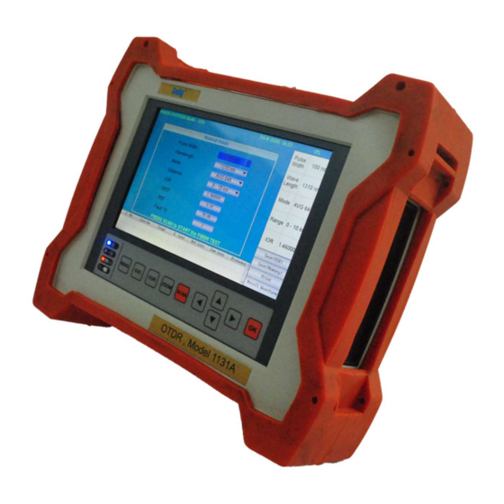
OTDR Features: OTDR stands for optical time domain reflectometer. The Model 1131 displays waveforms that you can use to detect fault locations in optical fiber cables and monitor fault conditions (transmission loss, splice loss, etc.). It is mainly used in the following optical fiber cable installation and maintenance situations. - Page 15 Press the cursor key once to initiate CURSOR 1, Press it again to initiate CURSOR 2. The cursors will indicate the exact location ( will also display the exact enabled the exact power if enabled during the purchase process ) at the location. The difference in power &...
-
Page 16: Measurement Mode
Measurement Mode : Auto Mode - This is the recommended mode for users who are not familiar with OTDR operation. In the Auto mode, OTDR parameters such as Range, Pulse Width, and Averaging Time are set automatically. In addition, Full Auto tests always include an Event Table and Summary Page. -
Page 17: Display Of The Distances To Breaks After Averaged Measurement
generated from connections or splice points but are buried in noise. The 1131 derives the measured data by averaging the specified number of optical pulse measurements or by averaging optical pulse measurements over the specified duration. During averaged measurement, you cannot change the measurement conditions. - Page 18 Optical Pulse Waveform Display The optical pulse applied to the optical fiber cable is reflected at different points of the optical fiber such as its connections, bent sections, and the open end of the fiber. These sections generate loss. The measured result is displayed as a waveform that has distance represented in the horizontal direction and loss level represented in the vertical direction.
- Page 19 Backscatter : When light travels through an optical fiber cable, Rayleigh scattering caused by changes in the density of materials that are smaller than the light’s wavelength and inconsistencies in the fiber's composition generates loss in the optical fiber itself. The portion of the scattered light that travels in the direction opposite to the direction of propagation is known as backscatter.
-
Page 20: Ghost Reflection
Ghost Reflections: Sometimes you will see a Fresnel reflection where you don't expect one—usually after the end of a fiber. This usually happens when a large reflection occurs in a short fiber. The reflected light actually bounces back and forth within the fiber, causing one or more false reflections to show up at multiple distances from the initial large (true) reflection. -
Page 21: Zooming The Waveform Display Scale
Zooming the Waveform Display Scale: You can zoom the displayed waveform in the direction of the optical power level (vertically) or in the direction of the distance (horizontally). ZOOM WAVEFORM DISPLAY SAMPLE WAVEFORM DISPLAY https://www.andigsystems.co.in... -
Page 22: Keypad Operations 22 To
Keypad Operations : MENU : Press to access the Main Menu which will let you select the AUTO , MANUAL mode & the settings menu. : Press once to return to the previous menu. Press one or more times, depending on which menu or editor submenu is displayed, to return to the Home page. - Page 23 SETTING : The ability to set the time, date & year, LCD brightness & format the internal storage is made available in this menu. HELP : To access the online manual saved in the OTDR memory. OTDR Sub Menu Soft Keys : ...
- Page 24 Print The user has the option of printing the screenshot if the printer is purchased as an additional accessory from ANDIG SYSTEMS. ANDIG uses proprietary printer hardware & hence this does not work with any standard printer. Kindly purchase the PRINTER from ANDIG only.
- Page 25 FILE TREE STRUCTURE ( Shown Below ): Recall Waveform / Detach Waveform : To recall the waveform, use the appropriate soft buttons on the bottom right of the screen using the up/down arrow keys. Please note , the equipment will store the non editable BMP ( picture format) of the screenshot along with the fiber trace file.
-
Page 26: Settings & Helpmenu
Cursor data This field displays A cursor location, B cursor location, field distance from A to B in user-selected Distance units, and measured loss between A and B in dBm Wavelength Displays test wavelengths of the currently displayed trace. field For the dual-wavelength test (VFL/1310 nm or 1310/1550 nm), press the [lambda] key to toggle between the VFL and 1310 nm test results or between the... - Page 27 Help Menu : Should you misplace / damage this manual, a brief explanation is uploaded into the memory of the equipment. This 14 page document is a ready reckoner for the user & can be accessed via the HELP menu in the main menu display page as shown below.
- Page 28 Connect the Fiber under test to the OTDR output port. o Select OTDR module o Select Auto / Manual Mode o Press “ SCAN” to start the test “ANDIG” Model 1131 is pre-calibrated at factory. No field calibration is required. https://www.andigsystems.co.in...
- Page 29 https://www.andigsystems.co.in...
- Page 30 Warranty ANDIG SYSTEMS warrants this instrument to be free of defects in parts and workmanship for one year from date of shipment (a six month limited warranty applies to sensors and cables). If it should become necessary to return the instrument for service during or beyond the warranty period.
Need help?
Do you have a question about the 1131A and is the answer not in the manual?
Questions and answers