Table of Contents
Advertisement
Quick Links
Advertisement
Table of Contents

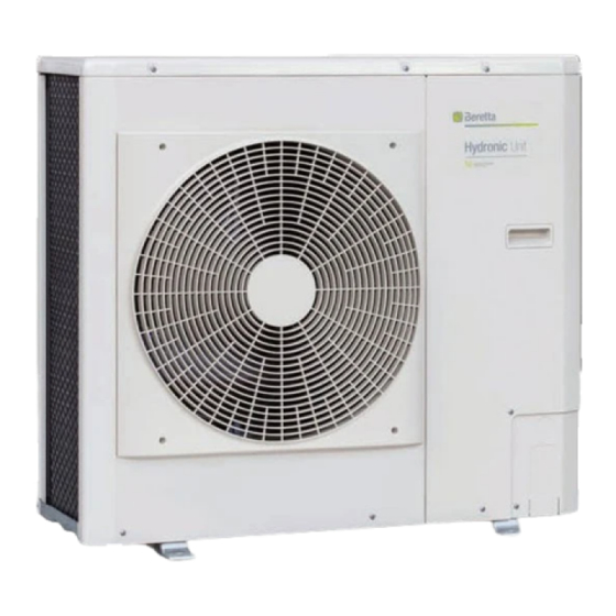
Summary of Contents for Beretta HYDRONIC UNIT B HE 5
- Page 1 Installer manual HYDRONIC UNIT B...
- Page 2 RoHS Directive 2011/65/EU • F-Gas Regulation 2014/517/EU • WEEE Directive 2012/19/EU RANGE Model Code HYDRONIC UNIT B HE 5 20161618 HYDRONIC UNIT B HE 7 20161619 HYDRONIC UNIT B HE 11 20161620 HYDRONIC UNIT B HE 15 20161621 HYDRONIC UNIT B HE 11T...
-
Page 3: Table Of Contents
HYDRONIC UNIT B TABLE OF CONTENTS GENERAL INFORMATION ....p. 4 General Notices ....... p. 4 Safety precautions . -
Page 4: General Information
GENERAL INFORMATION GENERAL INFORMATION This booklet is an integral part of the device, and must there- fore be carefully preserved, and must ALWAYS accompany it, even in the event that it is sold to another Owner or User, or is transferred to another system. -
Page 5: Unit Description
GENERAL INFORMATION Unit description B HYDRONIC UNIT B it is a range of heat pumps for the pro- duction of hot water for space heating, domestic hot water for do- mestic use (in combination with suitable boilers or exchangers) and cold water for cooling. -
Page 6: Layout
GENERAL INFORMATION Layout Model 5 - 7 Heat exchanger Circulation pump Fan protection grille Expansion vessel Front panel 10 Safety valve Compressor 11 Water inlet temperature probe Variable speed circulation pump 12 Pump release device Electrical box 13 Water outlet temperature probe Flow switch 14 Air bleeder valve Model 11 - 15... - Page 7 GENERAL INFORMATION Model 11T - 15T Heat exchanger Flow switch Fan protection grille Expansion vessel Front panel 10 Safety valve Compressor 11 Water inlet temperature probe Variable speed circulation pump 12 Pump release device Reverse cycle valve 13 Water outlet temperature probe Electrical box 14 Air bleeder valve...
-
Page 8: Technical Specifications
GENERAL INFORMATION 1.7 Technical specifications Model Cooling performance [A35 / W7] Nominal capacity 4,00 5,55 11,20 12,80 10,65 13,00 kW/kW 3,10 3,10 3,40 3,10 3,40 3,20 SEER kW/kW 4,85 5,75 5,15 5,00 5,40 5,25 Seasonal energy efficiency (ns) Cooling performance [A35/W18] Nominal capacity 4,85 8,00... -
Page 9: Performance Based On The Climatic Zone
GENERAL INFORMATION Performance based on the climatic zone Model Temperate zone - Average temperature [47 / 55 °C] Seasonal energy efficiency (ns) SCOP kW/kW 3,32 3,36 3,35 3,45 3,34 3,40 Pdesignh -7 °C 3,09 3,83 7,69 9,11 7,69 9,81 Pdesign at +2 °C 1,88 2,37 5,42... -
Page 10: Operating Limits
GENERAL INFORMATION Operating limits COOLING HEATING A (°C) A (°C) B (°C) B (°C) Outdoor air temperature Outdoor air temperature Supply water temperature Supply water temperature Model 5 1.10 Available static pressure HYDRONIC UNIT B it is equipped with a variable speed circulation For sizing the system, consider the residual head, shown below in pump. - Page 11 GENERAL INFORMATION MODEL 7 A (kPa) B (l/s) Available head pressure Water flow Medium speed High speed Low speed MODEL 11 - 15 A (kPa) B (l/s) Available head pressure Water flow Medium speed High speed Low speed...
-
Page 12: Refrigerant Circuit And Sensors Positioning
GENERAL INFORMATION 1.11 Refrigerant circuit and sensors positioning The cooling circuit is of the heat pump type with cycle inversion on mer the cycle is inverted and the thermal energy is extracted from the refrigerant gas. The source fluid used is the external air while the water, which cools down, and is transferred to the air. -
Page 13: Installation
The Instruction book comes with the equipment and it should be taken, read and kept carefully. Model The document envelope must be kept in a safe place. Any du- Packaging dimensions plicate must be requested from Beretta S.p.A. which reserves to charge the cost. 1500 1500 1500... -
Page 14: Handling And Removal Of The Packing
INSTALLATION Handling and removal of the packing • Follow the below instructions for packing removal: — transport the equipment in the installation place, using tools that can withstand the weight — remove the polyethylene film Before unpacking, personal protective clothing should be worn and used transport means and tools suitable for the size and —... -
Page 15: Recommended Distances
INSTALLATION If the unit is installed in a windy location, fit an anti-wind grille to protect the fan and check the correct functioning of the unit. Recommended distances The distances for the device installation and maintenance are prevent the airflow from being blocked, as well as to allow normal shown in the figure. -
Page 16: Positioning
INSTALLATION Multiple installations 1000 2000 1500 Measurements in mm. Positioning B HYDRONIC UNIT B devices must: — be positioned on a level surface that is capable of supporting their weight — be positioned on a sufficiently rigid surface that will not trans- mit any vibrations to the underlying or adjacent rooms It is recommended to place a rubber sheet between the insole and the appliance (60 shore hardness, 10 mm thick) or use appropri-... -
Page 17: Installation On Old Systems Or Systems In Need Of Upgrading
INSTALLATION 2.9.1 Plant water content place suitable for drainage. For correct operation of the appliance, a minimum volume of water must be guaranteed in the primary circuit of the system. The minimum volume is necessary to prevent the risk of ice formation during defrosting operations or the continuous mod- ulation of the compressor frequency. -
Page 18: Hydraulic Connections
INSTALLATION System scheme for heat pumps cascade HYDRONIC UNIT B External sensor (option) Temperature probe for cascade connection (accessory) Only units of the same model can be cascaded. 2.10 Hydraulic connections The size and positioning of the hydraulic connections of B MODEL 5 - 7 HYDRONIC UNIT B are shown in the following table. - Page 19 INSTALLATION If the unit works in a system with a boiler >(parallel installation) MODEL 11 - 15 when the boiler is working, make sure that the water tempera- ture inside the heat pump does not exceed 60 °C. Mandatory items: —...
- Page 20 INSTALLATION 2.10.1 Piping connections HYDRONIC UNIT B Factory connections Expansion vessel Field connections (for installer) Mesh filters (available as an option) 13 Calibration valve Plate heat exchanger Stop valves 14 Anti-vibration joint Temperature sensor Filling valve 15 Additional expansion vessel (if neces- Circulation pump 10 Pressure gauge sary)
-
Page 21: System Water Filling And Drainage
INSTALLATION 2.11 System water filling and drainage 2.11.2 System filling-up For the heat pump B HYDRONIC UNIT B a loading system is required. Before filling and emptying the system, set the main switch of the system and the main switch of the unit on "0" (off). O F F The filling pressure of the cold system must be 1.2 -1.5 bar. -
Page 22: Wiring Diagrams
INSTALLATION 2.12 Wiring diagrams Model 5 - 7 POWER CIRCUIT MOD. 005 MOD. 007 A001 Drive per variable speed PMV1 Electronic expansion valve motor Compressor Compressor discharge tempera- Outdoor air temperature sensor Fan motor ture sensor Suction temperature sensor Compressor thermal relay Condenser coil temperature sensor YV41 Cycle inversion valve... - Page 23 INSTALLATION CONTROL CIRCUIT POMPA PAROWNIKA A002 Main electronic board System flow temperature sensor SP90F Flussostato Command interface System return temperature sensor Suction temperature sensor EP90 Water pump Refrigerant temperature sensor YV41 Cycle inversion valve * consult the wiring diagram supplied with the unit...
- Page 24 INSTALLATION ELECTRICAL COMPONENTS POSITION A001 A002 A001 Drive per variable speed A002 Main electronic board SP90F Flussostato Compressor Compressor discharge temperature sensor EP90 Water pump Condenser coil temperature sensor Compressor thermal relay Outdoor air temperature sensor System flow temperature sensor Suction temperature sensor System return temperature sensor YV41 Cycle inversion valve...
- Page 25 INSTALLATION Model 11 - 15 POWER CIRCUIT A001 Drive per variable speed Compressor discharge temperature sensor Compressor Finned coil temperature sensor 1 Fan motor Finned coil temperature sensor 2 Fan motor Outdoor air temperature sensor Compressor thermal relay Suction temperature sensor PMV1 Electronic expansion valve motor YV41 Cycle inversion valve * consult the wiring diagram supplied with the unit...
- Page 26 INSTALLATION CONTROL CIRCUIT * * * POMPA PAROWNIKA A002 Main electronic board Command interface SP90F Flussostato EP90 Water pump Trasformer System flow temperature sensor Refrigerant temperature sensor System return temperature sensor Suction temperature sensor * consult the wiring diagram supplied with the unit...
- Page 27 INSTALLATION A002 Main electronic board Trasformer Compressor Compressor discharge temperature sensor Compressor thermal relay Finned coil temperature sensor 1 PMV1 Electronic expansion valve motor Finned coil temperature sensor 2 System flow temperature sensor Outdoor air temperature sensor System return temperature sensor Suction temperature sensor SP90F Flussostato YV41 Cycle inversion valve...
- Page 28 INSTALLATION Model 11T - 15T POWER CIRCUIT A001 Drive per variable speed Compressor Compressor discharge temperature sensor EP90 Water pump Finned coil temperature sensor 1 Fan motor Finned coil temperature sensor 2 Fan motor Outdoor air temperature sensor Compressor thermal relay Suction temperature sensor PMV1 Electronic expansion valve motor YV41 Cycle inversion valve...
- Page 29 INSTALLATION CONTROL CIRCUIT * * * POMPA PAROWNIKA A002 Main electronic board System return temperature sensor Command interface SP90F Flussostato EP90 Water pump Trasformer System flow temperature sensor Refrigerant temperature sensor * consult the wiring diagram supplied with the unit...
-
Page 30: Electrical Connections
INSTALLATION ELECTRICAL COMPONENTS POSITION A002 Main electronic board Trasformer Compressor Compressor discharge temperature sensor Compressor thermal relay Finned coil temperature sensor 1 PMV1 Electronic expansion valve motor Finned coil temperature sensor 2 System flow temperature sensor Outdoor air temperature sensor System return temperature sensor Suction temperature sensor SP90F Flussostato... - Page 31 INSTALLATION — put the system main switch on "OFF" and the equipment MODEL 5 - 7 main switch on "0" (off) Passing electrical connections — punch the connection points of the pre-cut part — remove the pre-cut part — remove the sharp edges from the hole —...
- Page 32 INSTALLATION use the following table: Model Electrical characteristics Power supply V/ph/Hz+N 230/1/50 400/3/50 Permitted voltage 220 - 240 380 - 415 Total power input 1,80 3,38 4,73 5,18 10,32 Cos Phi at max. power absorbed 0,98 Full load current 8,90 16,70 23,30 25,60...
- Page 33 INSTALLATION 2.13.1 Euxiliaries connections Comando CCN - Unità Polarità Parametro Funzione CCN+ WUI CCN+ / B+ RS485 Terra CCN CCN- WUI CCN - / B- DI#01- O /On Remoto DI#02- Ra reddamento/Riscaldamento (remoto) DI#03- Comfort /Eco(remote) P501 DI#04- Interruttore di sicurezza sfsw_typ cust_di5 P502...
- Page 34 INSTALLATION Connections for cascade heat pumps CCN-WUI CCN - / B- CCN+ WUI CCN+ / B+ CCN- WUI CCN - / B- CCN+ WUI CCN+ / B+ CCN-WUI CCN - / B- CCN+ WUI CCN+ / B+ JBUS - JBUS + WUI 0V WUI +12V CCN-WUI CCN - / B-...
-
Page 35: Control Panel (Accessory)
INSTALLATION 2.14 Control panel (ACCESSORY) The control panel is the interface for the Installer and the User to on the display. carry out all the operations for setting the operating parameters and The panel can be used to set the temperature required for the sys- displaying the status of the components present in the appliance. - Page 36 INSTALLATION Display Displays all the information necessary to manage the appliance. Days of the week 13 Lock settings Clock 14 Home, Night, Away mode Ambient temperature 15 Setpoint Water temperature 16 Electric heaters operation Advanced settings 17 Boiler operation Heating mode MON: Monday Cooling mode TUE: Tuesday...
- Page 37 INSTALLATION Display indication Description Temperature indication Ambient temperature Temperatura acqua Indication of parameter number and value Indication of the alarm code Indication that the occupation mode is blocked by the user. In this case, the time programming is deactivated. Indication that the mode "In casa" is active Indication that the mode "Notte"...
-
Page 38: Setpoint Parameters
INSTALLATION Fault codes Operating anomalies are signaled on the control panel display. PREVIOUS ALARM Fixed icon: indication of intervention of an alarm that has stopped the unit Flashing icon: indication of intervention of an alarm that has left the unit in operation •... - Page 39 INSTALLATION — push to select the desired parameter To change: — keep the key pressed for 2 seconds — push to change the value — push to confirm the selection and access the next item — keep the key pressed for 2 seconds to store the param- eter Finish the settings:...
-
Page 40: Fault Signals Description
INSTALLATION HYDRONIC UNIT B... - Page 41 HYDRONIC UNIT B INSTALLATION...
- Page 42 INSTALLATION HYDRONIC UNIT B...
-
Page 43: Parameters Overview
HYDRONIC UNIT B INSTALLATION... - Page 44 INSTALLATION HYDRONIC UNIT B...
- Page 45 HYDRONIC UNIT B INSTALLATION...
-
Page 46: Service Parameters
INSTALLATION HYDRONIC UNIT B... - Page 47 HYDRONIC UNIT B INSTALLATION...
- Page 48 INSTALLATION HYDRONIC UNIT B...
- Page 49 HYDRONIC UNIT B INSTALLATION...
-
Page 50: Configuration Parameters
INSTALLATION HYDRONIC UNIT B... - Page 51 HYDRONIC UNIT B INSTALLATION...
- Page 52 INSTALLATION HYDRONIC UNIT B...
- Page 53 HYDRONIC UNIT B INSTALLATION...
- Page 54 INSTALLATION HYDRONIC UNIT B...
- Page 55 HYDRONIC UNIT B INSTALLATION...
- Page 56 INSTALLATION HYDRONIC UNIT B...
- Page 57 HYDRONIC UNIT B INSTALLATION...
- Page 58 INSTALLATION HYDRONIC UNIT B...
-
Page 59: Commissioning
COMMISSIONING COMMISSIONING — the current consumed by the compressor is less than the maximum permitted — the device is operating under the recommended operating conditions 3.1 Preparation for first commissioning — the unit is able to stop and start up again — the pump water flow is included in the limits indicated in the The first commissioning must be carried out by the Technical chapter "Water flow"... -
Page 60: Functions
FUNCTIONS Functions 3.5.1 Acronyms Indoor Air Temperature BPHE Plate heat exchanger CHWS (Chiller Water System), system water circuito Domestic Hot Water Electric heater stage Entering Water Temperature (Fan Coil Unit), Fan Coil Unit Leaving Water Temperature New Hydronic Control Outdoor Air Temperature Pulse Modulating Valve Space Heating/Cooling Control Refrigerant Temperature... - Page 61 FUNCTIONS COOLING CLIMATIC CURVES OAT (°C) — If the OAT is valid (not transmitted by the inverter, value out perature. of range, etc.), the water setpoint is equal to the current min- The climatic curve corresponds to the water setpoint for the Home imum water temperature.
- Page 62 FUNCTIONS HEATING CLIMATIC CURVES (K7 AND K8) OAT (°C) — If the OAT is valid (not transmitted by the inverter, value out ature. of range, etc.), the water setpoint is equal to the maximum The climatic curve corresponds to the water setpoint for the Home current water temperature.
- Page 63 FUNCTIONS Control panel Water setpoint with direct access to the control panel Field Water setpoint from the parameter menu Field occupation Heating setpoint home 20 - 60°C Heating setpoint home [P401] 20 - 60°C Heating setpoint night 20 - 60°C Heating setpoint home [P401] + Offset heating night [P402] -10 a 0°C Heating setpoint home [P401] + Offset heating away...
- Page 64 FUNCTIONS Example: CUSTOMIZED HEATING CLIMATIC CURVES Default P585 P584 OAT (°C) P582 P583 — If the OAT is not valid, the water setpoint is equal to the max- imum personalized water temperature [P585]. — If the OAT is above the maximum current OAT threshold, the water setpoint is equal to the minimum personalized water temperature [P584].
- Page 65 FUNCTIONS Climatic curve offset (default and customized) Two other parameters are configurable to adjust the water setpoint curve (minimum cooling curve setpoint offset[P413]) according to customer needs: — and for the heating curve, the maximum heating water set- — for the cooling curve, the minimum cooling water set- point [P585] can be changed by an offset at the foot of the point[P589] can be changed by an offset at the foot of the curve (maximum heating curve setpoint offset [P412])
-
Page 66: Maintenance
MAINTENANCE MAINTENANCE Perform all level 1 operations, then perform: Electrical checks — At least once a year, tighten the electrical connections of the Ordinary maintenance power circuit (see table "Tightening torque for main electrical connections" p. 67 ). — If necessary, check and retighten all control / command con- To ensure maximum efficiency and reliability of the units, it is recom- nections (see table"Tightening torque for main electrical con- mended to establish a maintenance contract with your local service... -
Page 67: Tightening Torque For Main Electrical Connections
MAINTENANCE — One to two leak checks per year performed with a certified The compressor oil that is recovered during maintenance contains leak detector and a qualified person refrigerant and must be treated accordingly. The coolant under pressure must not be drained in the open air. —... -
Page 68: Refrigerant Volume
MAINTENANCE the assistance service. VFDs equipped with units do not require an insulation test, even if they are replaced; they are in fact checked systematically before delivery. In addition, the filter components installed in the VFD can distort the measurement and can also be damaged. If there is a need to check the insulation of the components of the appliance (fan motors and pumps, cables, etc.), the VFD must be disconnect- ed from the power circuit. - Page 69 BERETTA S.p.A. Via Risorgimento, 23/A 23900 LECCO Italy Tel. +39 0341 277111 Fax +39 0341 277263 info@berettaboilers.com www.berettaboilers.com As the manufacturer is constantly improving its products, the aesthetic or dimensional features, the technical data, the equipment and accessories indicated could be subject to var-...
Need help?
Do you have a question about the HYDRONIC UNIT B HE 5 and is the answer not in the manual?
Questions and answers