Table of Contents
Advertisement
Quick Links
Advertisement
Table of Contents

Subscribe to Our Youtube Channel
Summary of Contents for La Scossa Elettrica Bee Meter Duo
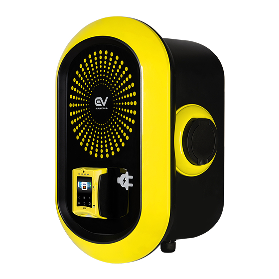
- Page 1 Bee Meter Duo User Manual...
- Page 2 CAUTION! Read this document before using the charger. Failure to follow any of the instructions or warnings in this document can result in fire, electrical shock, serious injury or death. The charger is designed only for charging of electric vehicles that support IEC 62196-1 and IEC 61851-1.
-
Page 3: Technical Specifications
Technical Specifications Max 3x32A* (22kW) Rated charging current per socket Less than 0.5W Consumption in idle state Allowed ambient temperature -25°C to +55°C Weather Resistant Degree of protection Dimensions (HxWxD) 52 x 36 x 26 cm Type 1 or 2 in accordance to Electric vehicle connector IEC 62196-2 for 32A Electric Power Supply... -
Page 4: Tools Required
Tools Required Name Remarks Electric (Bit preferred) Phillips screwdriver Electric (Bit preferred) Hex (M4) screwdriver Level Size M10 Stainless steel anchors X4 M10 to fit the anchors Stainless steel bolts X4 When the anchors are not Drill pre-inserted. 32A Type B Circuit Breaker X2 Type B 32A RCD X 2 Length as needed N2XY 5X6mm Cable X 2... -
Page 5: Installation
Installation Prerequisites This type of installation requires an electrical background. When unpacking contents of the kit, it is crucial to perform a visual check to confirm that none of the parts are damaged/broken. Prior to installation, make sure to disconnect the main circuit breaker (CB). - Page 6 There is risk of fire or electric shock. Do not alter, relocate, drill or remove any component without consulting with the Nayax certified team. Nayax is and will not be liable for any modifications or results of such modifications done to the product during or after installation. Installation must be carried out in dry conditions only.
- Page 7 Dismantle Internal Cable Press internal yellow cable, and dismantle front Panel. MJ - 0276 MJ - 0277 MJ - 0210 MJ - 0211 SIDE A SIDE B 3.0 10P F 3.0 10P M Connect External Power Cable Verify that the main circuit breaker (CB) is disconnected and that power is turned off Insert the external power cables via the hole (bottom of the charger) and secure it with PG.
- Page 8 Assemble Charger Fasten Cables using the black PG (bottom of the charger), Power UP CB, Close the front panel and fasten the ten screws using the Hex screwdriver. Attach to Wall Mount To attach the charger to the wall mount, place it firmly on the four hooks.
-
Page 9: Getting Started
Power-up Verify that the charger parts were not damaged during installation and/or that no wires are exposed. Make sure to follow all your local electrical regulations post installation. Turn on the main CB - Circuit Breaker (Switch I). Make sure that the charger unit turns on, indicated by the logo’s blue led light. - Page 10 Remove Nozzle Do not unplug the charger while charging. WARNING! Stop the charging process in the car. Release the latch on car's charge port (if applicable). Unplug the charger from the car. Close the car's charging port cover. Charging Status Screen The charging status is indicated by the different logo led lights and via the LCD screen (depending on the model).
-
Page 11: Troubleshooting
Troubleshooting If charging slows down / stops unexpectedly, what do I need to do? This could indicate of a few issues. Start by : Checking the car's infotainment for any error messages that could indicate what the exact issue is. Unplugging the charger from the car &... - Page 12 For further assistance, contact your local distributor at www.lascossaelettrica.it...
Need help?
Do you have a question about the Bee Meter Duo and is the answer not in the manual?
Questions and answers