Table of Contents
Advertisement
Quick Links
Welding camera system WVS-32
By semi-automatic or automatic welding equipment the service and control of the welding torch
mostly occurs from a control station. To set the position of the welding torch and the
parameters for the welding process optimally, however, a visual inspection from the control
station is required.
The welding camera WVS-32 provides a sharp color picture and allows therefore an optimal
observation of welding torch, filler wire and work piece as well as welding arc and melting
area. This can help you e.g., to shorten the set-up time substantially or faster recognition of
possible welding mistakes. The camera cables can be ordered up to 50 m length.
Version 1.4
1/7
WVS-32
Variovision, Pöttinger Straße 23, DE-82041 Oberhaching, www.variovision.tv, info@variovision.tv
Advertisement
Table of Contents

Related Manuals for VARIOVISION WVS-32

Summary of Contents for VARIOVISION WVS-32
- Page 1 The welding camera WVS-32 provides a sharp color picture and allows therefore an optimal observation of welding torch, filler wire and work piece as well as welding arc and melting area.
- Page 2 Table of content Reference.............................3 Safety instructions........................3 Delivered parts..........................4 Installation.............................4 Mounting............................4 Setting Iris.............................5 Focus adjust..........................5 Cooling............................5 Shield glass..........................5 WVS-32 princible wiring, Splitterbox separate................6 Technical specification.........................7 Spare parts...........................7 WVS-32 Variovision, Pöttinger Straße 23, DE-82041 Oberhaching, www.variovision.tv, info@variovision.tv...
- Page 3 Never try to repair a broken system by yourself, contact your dealer. Warranty will lost by inappropriate use of the system! Safety instructions Please read this manual carefully and check for the instruction before operating the WVS-32 welding vision system. Keep these instructions at a safe place.
- Page 4 For a mounting with possibility of change tilt position use adapter shown on right side. In this case the M8 screw has to be removed. On right and left side of base plate are also 1/4" -20 threads for mounting onto a tripod. WVS-32 Variovision, Pöttinger Straße 23, DE-82041 Oberhaching, www.variovision.tv, info@variovision.tv...
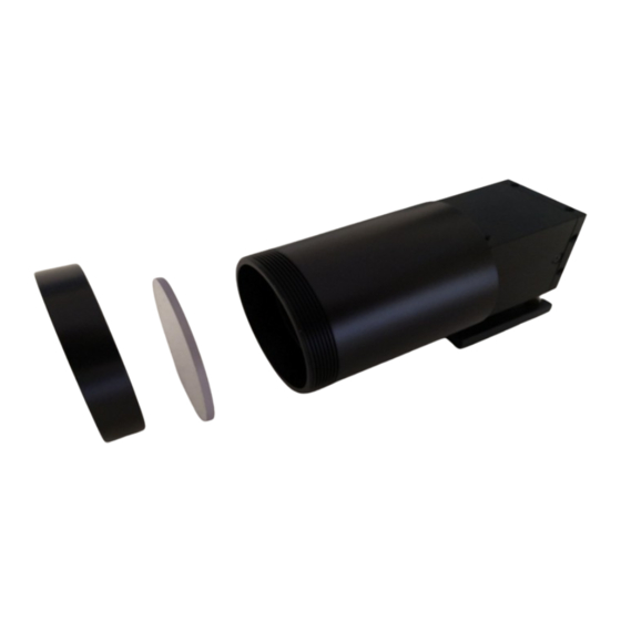
- Page 5 Tubes are connected to the two connectors on upper side Use tubes with 6mm o.D. Shield glass To protect the lens from spatters a Polycarbonate shield is used. For changing unscrew the nut from tube. WVS-32 Variovision, Pöttinger Straße 23, DE-82041 Oberhaching, www.variovision.tv, info@variovision.tv...
- Page 6 1= Video GND 4= 12 VDC GND 9-pol. Sub D, 6= Video + socket 9= 12 VDC + 401681 Splitterbox for WVS-32 camera BNC-cable 2m 402369-02 Monitor 15“ optional optional Power Supply 402501 WVS-32 Variovision, Pöttinger Straße 23, DE-82041 Oberhaching, www.variovision.tv, info@variovision.tv...
- Page 7 100 – 240 VAC to 12VDC Spare parts Description Cat.No. Shield glass 401676 Power supply 402501 Tel. +49 89 23967195 Variovision Thomas Stelzl Fax +49 89 23967196 Pöttinger Straße 23 www.variovision.tv DE-82041 Oberhaching info@variovision.tv www.weldingcamera.com WVS-32 Variovision, Pöttinger Straße 23, DE-82041 Oberhaching, www.variovision.tv, info@variovision.tv...
Need help?
Do you have a question about the WVS-32 and is the answer not in the manual?
Questions and answers