Table of Contents
Advertisement
Quick Links
About this Manual
Version No.: A/3
Release Date: April 25, 2016
© 2004-2016 Genrui Biotech Inc. All rights reserved.
Item No.: P01.91.300077-03
11000010 (WP21B)/11000013 (WP21E)
Statement
This manual will help you understand the operation and maintenance
of the product better. It is reminded that the product shall be used
strictly complying with this manual. User's operation failing to comply
with this manual may result in malfunction or accident for which Genrui
Biotech Inc. (hereinafter called Genrui) cannot be held liable.
Genrui owns the copyrights of this manual. Without prior written
consent of Genrui, any materials contained in this manual shall not be
photocopied, reproduced or translated into other languages.
Materials protected by the copyright law, including but not limited to
confidential information such as technical information and patent
information are contained in this manual, the user shall not disclose
such information to any irrelevant third party.
The user shall understand that nothing in this manual grants him,
expressly or implicitly, any right or license to use any of the intellectual
properties of Genrui.
Genrui reserves the right to modify and update this manual without
I
Advertisement
Table of Contents

Related Manuals for Genrui WP21B

Summary of Contents for Genrui WP21B
- Page 1 It is reminded that the product shall be used strictly complying with this manual. User’s operation failing to comply with this manual may result in malfunction or accident for which Genrui Biotech Inc. (hereinafter called Genrui) cannot be held liable.
- Page 2 Genrui reserves the final explanation right to this manual. Warning This system can only be operated by test professionals, doctors, lab workers or personnel for system maintenance and troubleshooting, who have been trained by Genrui. It is important for the hospital or organization that employs this equipment to carry out a reasonable maintenance schedule.
-
Page 3: Table Of Contents
Table of Contents Chapter 1 Brief Introduction .............. 1 Product overview ..............1 1.1.1 Brief introduction of this instrument ....... 1 1.1.2 Basic performance and parameters ....... 1 1.1.3 Product structure and composition ........ 3 1.1.4 Scope of application............3 Operation manual summary .......... - Page 4 Packing list ................12 Installation requirements ............. 12 Instrument Installation ............13 Chapter 4 Structure ................15 Front view of the instrument ..........15 Diagram of operation panel ..........15 Back view of the instrument ..........16 Menu interface ..............16 Chapter 5 Routine Operations ............
- Page 5 QC review ................35 Result review ............... 37 6.2.1 To edit samples ............37 6.2.2 To add results ............... 39 6.2.3 To search results ............41 Editing test items (Program) ..........43 6.3.1 To add an item and edit its parameters......43 System setup ...............
- Page 6 List of replaceable components ........... 62 Common faults and troubleshooting ........63 Chapter 8 Transportation and Storage ........... 66 Transportation ..............66 Storage ................66 Graphic explanations on the outer package ......66 Chapter 9 Commonly-used Consumables and Ordering Information ..................68 Appendix ...................
-
Page 7: Chapter 1 Brief Introduction
WP21 Series Operation Manual Chapter 1 Brief Introduction Chapter 1 Brief Introduction 1.1 Product overview 1.1.1 Brief introduction of this instrument Product name: Semi-auto Chemistry Analyzer Safety classification: Electric-Shock Safeguard Level I, Overvoltage Category II, Pollution Degree II Regulatory classification: A kind of biochemical analysis system in the category of analyzing instruments for clinical tests (6840), Regulatory Class II Operation mode: Continuous running... - Page 8 WP21 Series Operation Manual Chapter 1 Brief Introduction Absorbance At 340nm, the absorbance change in 20 stability minutes should not be greater than 0.005. It is expressed with coefficient of variation Absorbance (CV) and the value should not be greater repeatability than 1.0% Temperature...
-
Page 9: Product Structure And Composition
WP21 Series Operation Manual Chapter 1 Brief Introduction 1.1.3 Product structure and composition This instrument consists of a microprocessor, a main board, a power-supply system, a sampling system, a colorimetric system, a monitor and a printer. 1.1.4 Scope of application This instrument is applicable to quantitative analysis of clinical biochemistry items in medical institutions. -
Page 10: Screen Printing And Labels
WP21 Series Operation Manual Chapter 1 Brief Introduction Symbol Meaning May cause electric shock High temperature, which may lead to personal injury Strong light, which may lead to eye injury 1.3.2 Screen printing and labels The following screen printing and labels listed in the table below are applicable to this manual. -
Page 11: Figures
1.4 Warranty and service Genrui warrants that this product will be free from defects in materials and workmanship that occur within the warranty period. This warranty shall not apply to damages caused by the following situations: 1) Operation environment does not meet the specified requirements;... -
Page 12: Training
In order to help users properly use the analyzer and give full play to its performance, Genrui holds periodical free training for users throughout the world, please visit Genrui website or contact the local offices to get the training schedule. -
Page 13: Chapter 2 Safety And Precautions
2) Avoid spilling any liquid onto the instrument tabletop. If some liquid splashes into the analyzer, please cut off the power supply immediately and contact Genrui promptly. High Temperature 1) Before exchanging the bulb, please cut off the electricity and wait at least 30 minutes until the bulb cools down. -
Page 14: Precautions
Operators The analyzer can only be used by personnel who have been trained authorized Genrui representatives. Actions in Case of Breakdown If the instrument has a hazardous breakdown, such as fire, strange smell, smoke or other dangerous situations, anyone should directly cut off its electricity or the main power... - Page 15 Otherwise, the test results obtained may be inaccurate and the analyzer may be damaged. 2) If it is necessary to change its working environment, please contact Genrui or its distributor in your region. Electromagnetic Interference analyzer susceptible electromagnetic interference during running, which may influence the test results and lead to wrong operations.
- Page 16 3) The devices connecting with the COM RS232 port of this analyzer should satisfy the requirements in the National Standard GB 4793 of China. Analysis Parameters Incorrect analysis parameters may lead to false results. For more information, please consult Genrui or the reagent supplier.
-
Page 17: Chapter 3 Installation
Chapter 3 Installation 3.1 Instrument models This WP series can be divided into the following models: WP21B: Involving seven wavelengths, i.e. 340, 380, 405, 505, 546, 578 and 620nm; a type of semi-auto chemistry analyzer with touch screen WP21E: Involving six wavelengths, i.e. 340, 405, 505, 546, 578 and 620nm;... -
Page 18: Packing List
Chapter 3 Installation If the outer package is intact, please open the packaging box and check the items in the box at the presence of the distributor or Genrui personnel: 1) Verify if all the components are equipped according to the packing list. -
Page 19: Instrument Installation
WP21 Series Operation Manual Chapter 3 Installation analyzer 100-240V~, 50/60Hz, correctly grounded and the Power supply grounding impedance is less than 0.1Ω. Electromagnetic Do not close to an electric-brush engine or electric waves devices which are frequently switched on/off. 3.6 Instrument Installation 1) Open the special packaging box of this analyzer and carefully verify if the instrument and accessories in the box are consistent with the packing list. - Page 20 WP21 Series Operation Manual Chapter 3 Installation 8) If different devices need to cooperate together, to achieve some functions, a same reference potential is required, then it is necessary to connect all the isoelectric terminals. Isoelectric connection can inhibit potential difference, thereby eliminating electromagnetic interference.
-
Page 21: Chapter 4 Structure
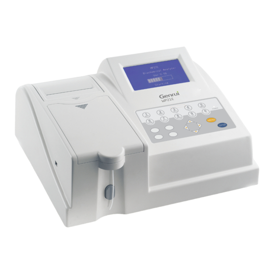
WP21 Series Operation Manual Chapter 4 Structure Chapter 4 Structure 4.1 Front view of the instrument Display screen Built-in thermal printer Sliding door at the housing cover Cuvettes Keyboard Figure 1 4.2 Diagram of operation panel Power indicator Number key Confirm key, Punctuation key used to confirm... -
Page 22: Back View Of The Instrument
WP21 Series Operation Manual Chapter 4 Structure 4.3 Back view of the instrument Housing fan Waste liquid pipe RS-232 serial port Power switch Power jack Isoelectric Peristaltic pump grounding rod Figure 3 4.4 Menu interface Note: For the operations mentioned below, if you use an instrument with a touch screen, you can click an appropriate icon or press the corresponding number key to perform the specific operation;... - Page 23 WP21 Series Operation Manual Chapter 4 Structure As illustrated in the figure above, the main interface displayed after instrument startup has six submenus, which can be selected with the number keys by operators. During routine work, operators mainly use Items 1 and 3; Item 1 can conduct the sample testing and Item 3 can help you view or print a report.
-
Page 24: Chapter 5 Routine Operations
WP21 Series Operation Manual Chapter 5 Routine Operation Chapter 5 Routine Operations 5.1 Measurement flowchart... -
Page 25: Routine Operations And Precautions
WP21 Series Operation Manual Chapter 5 Routine Operation 5.2 Routine operations and precautions Routine operations: 1) Startup: Turn on the power supply and enter the main interface after the system self-checking. Preheat the analyzer for more than 15 minutes. 2) To measure samples: Prepare the samples and reagents according to the reagent instruction. -
Page 26: Sample Measurement
WP21 Series Operation Manual Chapter 5 Routine Operation 5) Calibration should be performed during analysis to ensure the result accuracy. 6) The wastes generated should be regarded as medical wastes for disposal. 5.3 Sample measurement Press the number key “1” on the main menu to open the “Item Choice” window, as illustrated in Figure 5-1: Figure 5-1 Enter the desired item No. - Page 27 WP21 Series Operation Manual Chapter 5 Routine Operation After the light-source lamp becomes stable, the system will open the measurement interface, or you can press “Skip” to skip the preheating step and enter the measurement interface, as illustrated in Figure 5-3: Figure 5-3 First, by pressing the number key “1”, the system will automatically switch to the corresponding filter and test the original value of the...
- Page 28 WP21 Series Operation Manual Chapter 5 Routine Operation If the filter wheel switch succeeded, the screen is displayed as shown in Figure 5-5: Figure 5-5 If the filter wheel switch failed, the screen is displayed as shown in Figure 5-6: Figure 5-6...
-
Page 29: Aspirating The Cleaning Solution
WP21 Series Operation Manual Chapter 5 Routine Operation 5.3.1 Aspirating the cleaning solution After testing the dark current, the system will automatically enter the “Aspirate Cleaning Solution” interface, as illustrated in Figure 5-7: Figure 5-7 Operators can perform the following operations a) Place the cleaning solution (distilled water or sodium hypochlorite) onto the analyzer and press the number key “1”... -
Page 30: Aspirating Distilled Water
WP21 Series Operation Manual Chapter 5 Routine Operation 5.3.2 Aspirating distilled water After aspirating the cleaning solution, the system will automatically enter the “Aspirate Distilled Water” interface, as illustrated in Figure 5-8: Figure 5-8 Operators can perform the following operations: Place distilled water onto the analyzer and press the number key “1”... -
Page 31: Aspirating Blank Solution
WP21 Series Operation Manual Chapter 5 Routine Operation aspirate distilled water for calibration of absorbance zero-value. If the difference between the original value and zero value of distilled water is less than 1000, the system will display “Abnormal Light Path”. At this time, please check the light path. -
Page 32: Aspirating Standard Solution
WP21 Series Operation Manual Chapter 5 Routine Operation Figure 5-11 5.3.4 Aspirating standard solution When the system enters the “Aspirate Standard Solution” interface, if there is only one calibrator value, the screen is displayed as Figure 5-12: Figure 5-12 After placing the standard solution onto the analyzer, press the number key “1”, the instrument will begin to aspirate the standard solution. -
Page 33: Aspirating Sample Solution
WP21 Series Operation Manual Chapter 5 Routine Operation Figure 5-13 5.3.5 Aspirating sample solution If the analyzer has tested the blank and standard solutions for this item, then after measurement of the sample solution, the system will directly enter into the testing interface for next sample, as illustrated in Figure 5-14. -
Page 34: Standby Status
WP21 Series Operation Manual Chapter 5 Routine Operation will automatically measure the next patient sample under the same test item. Figure 5-15 If the item is tested by the kinetic method, the screen will dynamically display the reaction curve during measurement of the standard and sample, as illustrated in Figure 5-16: Figure 5-16 The results are displayed in the same way as other measurement... -
Page 35: Setup
WP21 Series Operation Manual Chapter 5 Routine Operation displayed as shown in Figure 5-17. Ten minutes later, the monitor backlight will shut down. Figure 5-17 Press any key on the standby interface to return to the last interface before standby. 5.3.7 Setup In the “Measure”... - Page 36 WP21 Series Operation Manual Chapter 5 Routine Operation See details in 6.4.1. 5.3.7.2 Item editing See details in 6.3.1.2. 5.3.7.3 Sample editing See details in 6.2.1. 5.3.7.4 QC editing Press the number key “4” on the “Set” interface to display a screen like Figure 5-19: Figure 5-19 In the “Edit QC”...
-
Page 37: Search
WP21 Series Operation Manual Chapter 5 Routine Operation c) Target value Operation: Press the number key “1” to set the value. 5.3.7.5 Mode switching Press the number key “5” and display a screen like Figure 5-20: Figure 5-20 Normal: The mode for measurement of patient samples. QC: The mode for measurement of QC. - Page 38 WP21 Series Operation Manual Chapter 5 Routine Operation Sample volume: 500μL Temperature: 37℃ Decimal places: 0 Unit: μ/L Blank: No Wavelength 1: 340 Sampling points: 2 Normal value (high): 40 Normal value (low): 0 Correction: 1.000, 0.00 Calibration: No Linear range: <500 Delay time: 30S Interval time: 40S Factor: 1746.0...
- Page 39 WP21 Series Operation Manual Chapter 5 Routine Operation Figure 5-21 II. Determination of total protein by end-point method 1) Set the following parameters of this item in the “Program” menu according to the reagent instruction: Name: TP Method: End-point method Number of wavelengths: 1 Temperature: 37℃...
- Page 40 WP21 Series Operation Manual Chapter 5 Routine Operation screen will display “ASP Rinse”. Place the cleaning solution onto the analyzer and press the key “1” to start the washing operation. 3) After completion, the screen displays “ASP DI Water”. Place distilled water onto the instrument and press “1”...
-
Page 41: Chapter 6 Software Operation
WP21 Series Operation Manual Chapter 6 Software Operation Chapter 6 Software Operation 6.1 QC review Quality controls are used to examine and control the instrument precision during assay, monitor the changes of stability, improve the result consistency for inter- and intra-batch samples during routine assay, and thus finally ensure the reliability of test results for every patient sample. - Page 42 WP21 Series Operation Manual Chapter 6 Software Operation displayed as Figure 6-2: Figure 6-2 Press to browse the results. Press the number key “1” to print the results. Press the number key “2” to delete currently displayed results. Press “Exit” to return to the previous interface. c) Statistics Press the number key “3”...
-
Page 43: Result Review
WP21 Series Operation Manual Chapter 6 Software Operation Press the number key “1” to change the target value. Press the number key “2” to print the statistical results. Press “Exit” to return to the previous interface. 6.2 Result review Press the number key “3” on the main menu and display a screen like Figure 6-4: Figure 6-4 6.2.1 To edit samples... - Page 44 WP21 Series Operation Manual Chapter 6 Software Operation Figure 6-5 You can edit the information about patient samples on the sample editing interface, and the specific operations are described as follows: 6.2.1.1 No. If you need to measure another test item for the same patient, change the current “No.”...
-
Page 45: To Add Results
WP21 Series Operation Manual Chapter 6 Software Operation 6.2.1.5 Blood group Operation: Use left and right cursor keys to choose Options: (None), A, B, AB, O, RH+, RH- 6.2.2 To add results Some test items must be completed by other instruments, but the results should be stored or printed with those obtained in this analyzer. - Page 46 WP21 Series Operation Manual Chapter 6 Software Operation 1) No. If you need to measure another test item for the same patient, change the current “No.” to the original “No.” of this patient. 2) ID The ID number can be freely revised in the range of 1~99999999999999, but repetition is not allowable.
-
Page 47: To Search Results
WP21 Series Operation Manual Chapter 6 Software Operation 9) Unit Operation: Use left and right cursor keys to choose Options: μ/L, μ/mL, μmol/L, mmol/L, g/L, mg/L, g/dL, g/mL, X10 12/dL, ABS If you enter a patient number that does not exist, the system will display “This No. - Page 48 WP21 Series Operation Manual Chapter 6 Software Operation 3) Printing Operation: Press the number key “1” to print all the results of the currently displayed “No.”. 4) Searching Operation: Press the number key “2” to view all the results of the currently displayed sample number.
-
Page 49: Editing Test Items (Program)
WP21 Series Operation Manual Chapter 6 Software Operation 6.3 Editing test items (Program) Press the number key “4” on the main interface to display a screen as shown in Figure 6-9: Figure 6-9 6.3.1 To add an item and edit its parameters 6.3.1.1 To add an item Press the up and down cursor keys to jump to the desired page. - Page 50 WP21 Series Operation Manual Chapter 6 Software Operation 6.3.1.2 To set up the item parameters In an interface as illustrated in Figure 6-9, press the number key of the corresponding item to open the “Program” window like Figure 6-11:...
- Page 51 WP21 Series Operation Manual Chapter 6 Software Operation Figure 6-11 You can set up the following parameters in the “Program” window: Method Operation: Use left and right cursor keys to choose...
- Page 52 WP21 Series Operation Manual Chapter 6 Software Operation Options: End-point [E], two-point, kinetics [K], cutoff [C], division [D] Wavelength Operation: Use left and right cursor keys to choose Options: 1 or 2 Temperature Operation: Use left and right cursor keys to choose Options: 37℃, 30℃, room temperature ...
- Page 53 WP21 Series Operation Manual Chapter 6 Software Operation Wavelength Operation: Use left and right cursor keys to choose Options: 340nm, 380nm, 405 nm, 505 nm, 546 nm, 578 nm, 620 nm Sampling points Operation: Use left and right cursor keys to choose Note: The setting range of the kinetic [K] method is 3 –...
- Page 54 WP21 Series Operation Manual Chapter 6 Software Operation Interval time Operation: Press the number key “1” to set the value. Standard values Operation: Press the number key “1” to set the value. Attached explanation: If the measurement method is set as “division [D]”, the screen will be displayed as Figure 6-12 below: Figure 6-12 Note: “Y=A/B”...
- Page 55 WP21 Series Operation Manual Chapter 6 Software Operation Figure 6-13 Note: “Y=A+B+C-D-E-F” is a formula, in which A, B, C, D, E and F represent two related items that have been tested After completion of editing or pressing “Exit”, display a screen like Figure 6-14: Figure 6-14 Press “1”...
-
Page 56: System Setup
WP21 Series Operation Manual Chapter 6 Software Operation 6.4 System setup Press the number key “5” on the main interface to enter the system setup interface. The screen is displayed as Figure 6-15: Figure 6-15 6.4.1 Printing setup Press the number key “1” on the “Setup” interface to display a screen like Figure 6-16: Figure 6-16 Press “1”... -
Page 57: Time Setup
WP21 Series Operation Manual Chapter 6 Software Operation Press “2” to select or cancel this option. When the option is checked, if you use the kinetics method to measure samples, the instrument will automatically print the reaction curve after measuring a patient’s sample. -
Page 58: Com Setup
WP21 Series Operation Manual Chapter 6 Software Operation 6.4.3 COM setup In the system setup interface, press “3” to open the “COM” window. The screen is displayed as Figure 6-18: Figure 6-18 You can set the parameters for COM communication. Press left and right keys to select the desired parameters. -
Page 59: System Maintenance
WP21 Series Operation Manual Chapter 6 Software Operation Figure 6-19 Adjust the backlight as needed by pressing the up, down, left and right keys on the keyboard. 6.5 System maintenance Press the number key “6” on the main interface to open the “Maintain” window. -
Page 60: Aspiration Volume Setting
WP21 Series Operation Manual Chapter 6 Software Operation Figure 6-21 Press the up, down, left and right keys on the keyboard to set the parameters. “TEMP” is used to observe the real-time temperature changes of colorimetric cells during running. For “Set TEMP”, you have two options: 30℃ and 37℃. “ADJ”... -
Page 61: Aspiration Adjustment
WP21 Series Operation Manual Chapter 6 Software Operation Figure 6-22 By using this function, you can arbitrarily set the “Clean VOL” and “Sample VOL” in the range of 0~9999μL. The set cleaning volume must ensure that the pipelines are clean after washing. The default value of “Clean VOL”... -
Page 62: Absorbance Testing
WP21 Series Operation Manual Chapter 6 Software Operation “Sample” to start aspiration and observe whether the aspirated volume is accurate. If the sample after aspiration is exhausted, increase the value in “Real VOL”; if the sample after aspiration remains a large amount, decrease the value in “Real VOL”. - Page 63 WP21 Series Operation Manual Chapter 6 Software Operation Figure 6-24 Please operate according to the prompts on the screen. Absorbance testing is to allow the system to determine the absorbance changes in different periods and correct accordingly, thereby making the results more reliable.
-
Page 64: Adc Adjustment
WP21 Series Operation Manual Chapter 6 Software Operation 6.5.5 ADC adjustment In the “Maintain” interface, press “5” to open the “ADC ADJ” window. The screen is displayed as Figure 6-25: Figure 6-25 Press to set the parameters. Press to switch among the set parameters. Place distilled water onto the instrument and click “Sample”... -
Page 65: Restoration Setting
WP21 Series Operation Manual Chapter 6 Software Operation 6.5.6 Restoration setting In the “Maintain” interface, press “6” to open the “Restore” window. The screen is displayed as Figure 6-26: Figure 6-26 1) To delete results Press “1” to delete all the patient results stored in the instrument. 2) To delete QC Press “2”... -
Page 66: Chapter 7 Daily Use And Maintenance
WP21 Series Operation Manual Chapter 7 Daily Use and Maintenance Chapter 7 Daily Use and Maintenance In order to maximize the analyzer’s performance, ensure its reliability and extend its service life, please perform maintenance and service in strict accordance with the requirements in this chapter. 7.1 Daily maintenance and care 1) Use method of keyboard The instrument keyboard is a type of slight-touch product;... -
Page 67: Explanation About Elimination Or Reduction Of Instrument Downtime
75% alcohol. Otherwise, touching the instrument’s surface may cause biological risks such as infection. If a large amount of liquid splashes and penetrates into the analyzer, please stop using the instrument and pull out the power plug, and then contact Genrui or local representative. -
Page 68: Preventive Maintenance And Inspection For Safety Purpose
If the instrument is crashed or dropped, whether there is obvious damage on its surface or inside, stop using it and contact Genrui or local representative. 3) If there is an instrument breakdown after the warranty period, ask Genrui’s service engineer, reparation engineer in the device... -
Page 69: Common Faults And Troubleshooting
WP21 Series Operation Manual Chapter 7 Daily Use and Maintenance Parts: None 2) List of parts that should be replaced by authorized service engineers Fuse, with specifications of F3A250V Power supply and the switch PCB hardware system 7.5 Common faults and troubleshooting Fault Cause Analysis Troubleshooting... - Page 70 WP21 Series Operation Manual Chapter 7 Daily Use and Maintenance Fault Cause Analysis Troubleshooting Description The screen is The display contrast Adjust the contrast blurred or too of the LCD changes regulator inside the dark with the environment instrument The printer 1.
- Page 71 WP21 Series Operation Manual Chapter 7 Daily Use and Maintenance Fault Cause Analysis Troubleshooting Description A There are air bubbles in the cuvette B The cuvette is unclean C The light-source lamp is ageing Unstable test 1. Not test 1. Test absorbance during results absorbance system maintenance...
-
Page 72: Chapter 8 Transportation And Storage
WP21 Series Operation Manual Chapter 8 Shipment and Storage Chapter 8 Transportation and Storage 8.1 Transportation This analyzer can be delivered by general transportation; however, fierce impact, vibration, or exposure in rain or snow should be avoided during shipment. Please make sure to place and transport the instrument as per the related graphics on its outer packaging box. - Page 73 WP21 Series Operation Manual Chapter 8 Shipment and Storage ——“Humidity limit”: Humidity limit for transportation and storage environment. ——“Temperature limit”: Temperature limit for transportation and storage environment. Note: The illustrations are for reference only, subject to pictures on the outer package.
-
Page 74: Chapter 9 Commonly-Used Consumables And Ordering Information
WP21 Series Operation Manual Chapter 9 Commonly-used Consumables and Ordering Information Chapter 9 Commonly-used Consumables and Ordering Information During normal use and maintenance of this Semi-auto Chemistry Analyzer, the required consumables are listed as follows: Name Specification Thermal 80mm × 35mm printing paper Light-source... - Page 75 WP21 Series Operation Manual Chapter 9 Commonly-used Consumables and Ordering Information Name Specification Filter 405nm Filter 505nm Filter 546nm Filter 578nm Filter 620nm Filter 700nm 1.8m, three-core power Power cable cable compliant with the national standard in China 3A, φ5mm × 20mm Fuse Ordering method Order via the local distributors of the consumable materials.
-
Page 76: Appendix
WP21 Series Operation Manual Appendix Appendix Appendix 1 Replace printing paper 1. Open the printer cover and remove the roller (first take out the terminal without gears and then the other terminal with gears; please handle them gently), and take out the residual printing paper. -
Page 77: Appendix 2 Replace Pump Tubes
WP21 Series Operation Manual Appendix 5. Pull out the printing paper from the paper outlet at the printer cover and close the cover. Note: The “Feed” key is available on the main interface, all the screens waiting for keyboard entering, the “Print/Delete Result Reports”... -
Page 78: Appendix 3 Clean The Cuvette
WP21 Series Operation Manual Appendix Housing Peristaltic pump tube Waste liquid pipe Bottom Liquid plate Finger-like Pump tube Peristaltic inlet pipe rack of the connector pump liquid tube Figure 13-1 Structure of the peristaltic pump Appendix 3 Clean the cuvette 1. -
Page 79: Appendix 4 Com Communication
WP21 Series Operation Manual Appendix Appendix 4 COM communication Hardware conditions: Connect the RS-232C ports of the two instruments needing to be communicated by RS-232C cable, or connect the instrument with the COM port of the computer. This instrument provides the following options about COM status: Connection: If you want to perform data exchanges with a computer, please connect a standard RS-232 cable with the “COM RS232 1”... - Page 80 WP21 Series Operation Manual Appendix Explanation about COM communication: 1. All the data sent is encoded with Code ASCII, e.g. using COM tools to switch to the character format. 2. Each item name or number is followed at least one blank space Analysis of a typical frame: After printing assay results or measuring a sample and QC, the instrument will send a series of character data from the RS-232 serial...
-
Page 81: Appendix 5 List Of Test Items And Test Combinations
WP21 Series Operation Manual Appendix Item abbreviation: ALT Measurement result: 1.08 Unit: μ/mL Range: 1.20--2.31 Frame tail: 03H Appendix 5 List of test items and test combinations The following 54 test items are built in this instrument: Item Item Abbreviation Name Abbreviation Name... - Page 82 WP21 Series Operation Manual Appendix Item Item Abbreviation Name Abbreviation Name Blood urea Red blood nitrogen cell count Creatinine Globulin Albumin/ Uric acid globulin ratio Carbon-dioxid Indirect e combining UDBIL bilirubin power Immuno- Blood ammonia globulin G Immuno- Blood glucose globulin M Total Compleme...
- Page 83 WP21 Series Operation Manual Appendix Item Item Abbreviation Name Abbreviation Name Monoamine Serum calcium oxidase Each test item should be tested with the corresponding reagent kit. The test combinations built-in this instrument and their respective test items are as follows: Alanine transaminase, alkaline phosphatase, glutamic oxaloacetic transaminase, γ-glutamyl transpeptidase, total protein, albumin, total...
-
Page 84: Appendix 6 Hazardous Substances
WP21 Series Operation Manual Appendix red-blood-cell count, lipase, monoamine oxidase Appendix 6 Hazardous substances Hazardous substances Parts name Cr(VI) PBDE ○ ○ ○ ○ ○ ○ Host shell ×(1) ○ ○ ○ ○ ○ Host PCBA ○ ○ ○ ○ ○... - Page 85 WP21 Series Operation Manual Appendix Hazardous substances Parts name Cr(VI) PBDE ○ ○ ○ ○ ○ ○ Maintenance tools Inlet transfer assembly ○ ○ ○ ○ ○ ○ Package Packaging materials ○: means the content of the hazardous substance in all homogeneous materials of the part is in the limited requirement according to the standard of SJ/T 11363-2006.
Need help?
Do you have a question about the WP21B and is the answer not in the manual?
Questions and answers