Table of Contents
Advertisement
Quick Links
Advertisement
Table of Contents

Related Manuals for id LAB FOTOMETER 2008

Summary of Contents for id LAB FOTOMETER 2008
- Page 1 FOTOMETER 2008 STD (Light attenuation meter users guide)
- Page 2 DEVICE DESCRIPTION ............................ 3 SAFETY RULES..............................3 SETTING UP THE DEVICE..........................3 DISPLAY CONTENT ............................4 OPERATING DEVICE IN AUTOMATIC MODE ................... 5 ........................5 WITCHING TO AUTOMATIC MODE ........................5 WITCHING BACK TO MANUAL MODE OPERATING DEVICE IN MANUAL MODE ....................5 ..........................
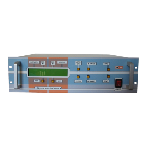
- Page 3 Device description Light attenuation meter FOTOMETER 2008 consists of modulated light source, lock- in type light detector and control unit. Device measures intensity of light traveling from the light source to the light detector. It makes the device suitable for measurement changes of attenuation of light in the area between the light source and the light detector.
- Page 4 Display content Display on control unit shows measured light intensity value as well as other related information like actual range, measurement mode, selected input filter and so on. The layout of the display is described in the table below. Switching status Mode Overflow status Range number...
- Page 5 Operating device in automatic mode In automatic mode the device switch to more sensitive range, when intensity value decrease below 8 percent of current range. When intensity rise over 100 percent of current range, device automatically switches to less sensitive range. During switching device displays SWITCHING message on the display.
- Page 6 Setting reference To set reference press SET button bellow the reference you want to set. Current intensity value is stored as reference value. Using input filter Light detector has two input filters. Fast filter is intended for measurement of values changeable in time.
- Page 7 • Attach connectors back to its place. Be careful not to swap two same size connectors. One marked as MOTOR connect to the chopper motor. Other connectors can not be swapped. • Slide the cylindrical side cover and the back cover to its place and fasten it using four screws.
Need help?
Do you have a question about the FOTOMETER 2008 and is the answer not in the manual?
Questions and answers